Battery
Inkplate 10 runs from USB or from a single-cell Li-ion or Li-Po battery, and it has a charger on board. Plug a battery into the 2-pin JST connector, and the board charges it whenever USB is connected. This page follows the board version 1.3.1 schematic. The board sold as SKU 333241 comes without a battery.
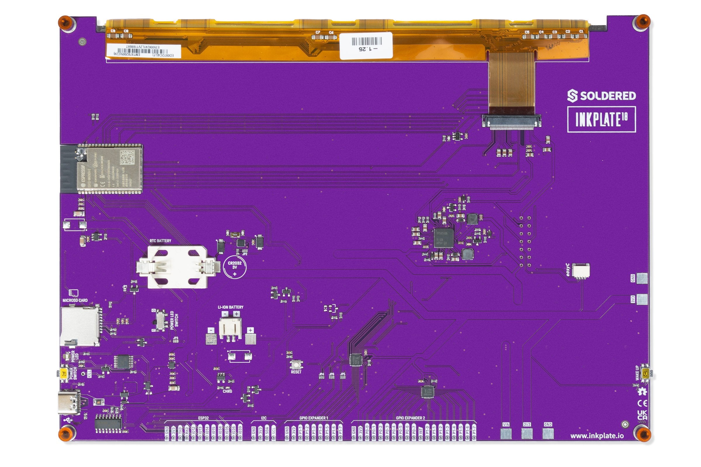
Check the polarity before you plug a battery in. The library README warns that some batteries sold online have reversed polarity, and that this can damage the Inkplate board. A pouch battery from soldered.com is safe.
Battery connector
| Item | Details |
|---|---|
| Connector | 2-pin JST, 2.00 mm pitch |
| Pin 1 | +, the battery positive (VBAT) |
| Pin 2 | -, GND |
| Supported batteries | Standard Li-ion or Li-Po, 3.7 V nominal. The battery voltage example names a 3.6 to 4.2 V battery. |
| Not a power source | The CR2032 coin cell holder. That cell is only a backup for the RTC (real-time clock) and cannot power the board. |
Compatible batteries
The library README lists standard Li-ion and Li-Po batteries with a 3.7 V nominal voltage as supported. It also says you can use a battery of any size or capacity when the board is not in an enclosure. The Soldered pouch batteries are the ones the README names as safe for polarity.
🔗Li-ion batteries on soldered.com
Battery collection linked from the library README
The Inkplate 10 with enclosure and battery (SKU 333247) ships with a battery and an enclosure. See the enclosure page for the dimensions.
Charging
An MCP73831 charge controller (a single-cell Li-ion charger chip from Microchip) charges the battery from the USB supply. Charging starts on its own when you plug in a USB cable with a battery connected. When you unplug USB, the board runs from the battery.
| Item | Details |
|---|---|
| Charger chip | MCP73831 |
| Supply | USB (VUSB) |
| Charge current | 400 mA, set by a 2.49 kΩ resistor on the charger's PROG pin. |
| Charge LED | A red LED, driven by the charger's STAT output, shows the charging status. |
For the full charging profile, termination and protection features, see the MCP73831 datasheet from Microchip.
Measuring the battery voltage
The ESP32 reads the battery voltage on IO35. A divider of two 100 kΩ resistors halves the voltage, so a full 4.2 V cell shows up as 2.1 V on the pin.
The divider does not stay connected. A pair of transistors switches it on only while a reading is taken, so the divider does not draw current from the battery the rest of the time. GPIO expander 1 pin P1-1 drives those transistors through solder jumper JP6.
| Part | Role |
|---|---|
IO35 | ESP32 analog input that reads the divided battery voltage |
| Two 100 kΩ resistors | Divide the battery voltage by two |
Expander 1 P1-1 | Switches the divider on and off |
JP6 | Connects P1-1 to the divider switch by default. See the jumpers page. |
In the Arduino library, readBattery() does all of this for you. It switches the divider on, waits 5 ms, reads IO35 and switches the divider off again. The battery voltage example shows it in a complete sketch.
If you move JP6 to pads 2 and 3 to free P1-1 on the header, expander 1 can no longer switch the divider, and readBattery() stops returning a valid voltage. The free GPIO page lists the other pins the board already uses.