Hardware Details
Power comes in on the USB-C receptacle and passes through the slide switch to
the HUSB238. The HUSB238 is a USB Power Delivery sink controller: it tells the
charger which voltage and current to supply, then drives a P-channel MOSFET
that switches that voltage through to VOUT. The board brings out:
- The output,
VOUTandGND, on a 5.0 mm screw terminal and on two single 2.54 mm pins. - The I2C lines,
SDA,SCLandGND, on a 3-pin header. - Two DIP switch banks, one for the voltage and one for the current request.
Key specifications
| Specification | Value |
|---|---|
| Interface | |
| Interface | I2C |
| Qwiic compatible | No |
| Default I2C address | 0x08 |
| Address changeable | No |
| Breadboard compatible | Yes |
| Voltage request | 5, 9, 12, 15, 18 or 20 V, by DIP switch or I2C |
| Current request | 1.25, 1.5, 2, 2.5, 3 or 3.25 A, by DIP switch or I2C |
| Power | |
| Output voltage | 5 to 20 V, as negotiated with the USB-C PD charger |
| Maximum output current | 3.25 A |
| Logic level | SDA and SCL 2.5 to 5.5 V (3.3 V or 5 V controllers) |
| Protection | Output off above 1.2 times the requested voltage; falls back to 5 V at 150 °C junction temperature |
| Output switch | AO4459 P-channel MOSFET, 30 V |
| Other | |
| Controller IC | HUSB238 (HUSB238_002DD), USB PD 3.0 sink |
| Indicator | Purple LED on VOUT, disabled by cutting JP1 |
| Power switch | Slide switch between USB-C VBUS and the board |
| Dimensions | 54 x 22 mm |
| Mounting holes | 2x 3.2 mm |
Pinout
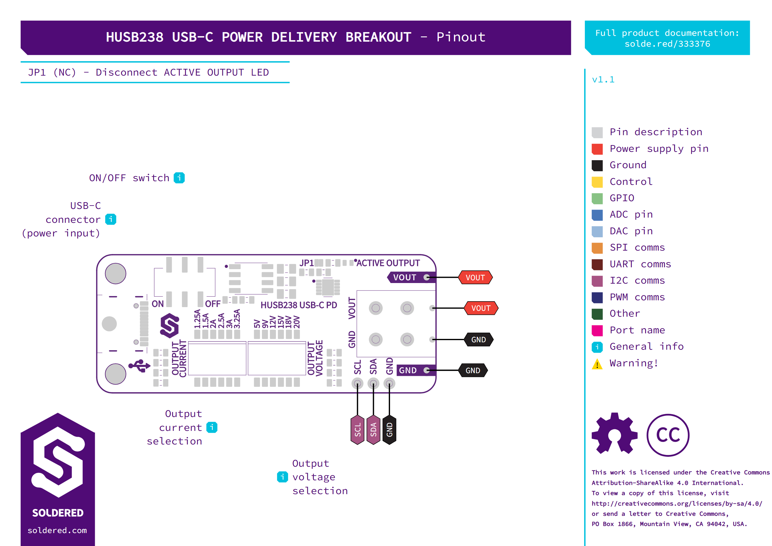
| Pin | Pin name | Description |
|---|---|---|
VOUT | Output | The negotiated voltage, 5 to 20 V, on the screw terminal and on a single 2.54 mm pin. |
GND | Output ground | Ground for the output, on the screw terminal and on a single 2.54 mm pin. |
SDA | I2C data | I2C data line of the HUSB238, on the 3-pin header. No pull-up on the board. |
SCL | I2C clock | I2C clock line of the HUSB238, on the 3-pin header. No pull-up on the board. |
GND | Ground | Ground on the 3-pin header, for the I2C connection. |
| USB-C | Input | Power from a USB-C PD charger, through the slide switch. |
Voltage and logic levels
| Connection | Supported voltage | Notes |
|---|---|---|
| USB-C input | 5 to 20 V from the charger | The HUSB238 operates from 3 V to 25 V and is rated 30 V on its supply input. |
VOUT | 5, 9, 12, 15, 18 or 20 V | Up to 3.25 A. Turns off when the input rises above 1.2 times the requested voltage. |
SDA, SCL | 2.5 to 5.5 V | Works with 3.3 V and 5 V controllers. No pull-up resistors on the board. |
The HUSB238 takes its power from USB-C, not from the I2C header, so it answers on I2C only while a charger is plugged in and the slide switch is on. If the chip gets too hot, it falls back to 5 V at 150 °C junction temperature.
VOUT can be as high as 20 V. Check which voltage the board is set to before
you connect a load, and never connect VOUT to a controller's 3.3 V or 5 V
pins.
Voltage and current switches
One DIP switch bank sets the voltage and the other sets the current request.
The board marks them OUTPUT VOLTAGE and OUTPUT CURRENT and prints each
switch's value next to it. Each bank has six switches, one per value. With the
USB-C connector on the left, the printed values run left to right:
| Bank | Printed values, left to right |
|---|---|
OUTPUT VOLTAGE | 5V, 9V, 12V, 15V, 18V, 20V |
OUTPUT CURRENT | 1.25A, 1.5A, 2A, 2.5A, 3A, 3.25A |
With every switch off, the board asks for 20 V and 3.25 A.
If the switches select a setting that is not allowed, such as 5 V and 12 V on together, the board falls back to its default request: 20 V if the charger offers it, otherwise the next lower voltage the charger does offer. The current bank works the same way, with 3.25 A as its default.
Voltage and current can also be requested over I2C, but the Soldered libraries only request a voltage, so set the current on the DIP switches.
If the charger does not offer the voltage you set, the HUSB238 takes the next lower one it does offer. Over I2C, the Arduino and MicroPython libraries can request a different voltage while the board runs: see the Request a voltage pages in each library.
Dimensions
The board measures 54 x 22 mm and has two 3.2 mm mounting holes.
Jumpers
| Jumper | Default | Function |
|---|---|---|
| JP1 | Closed | Connects the purple output LED to VOUT. Cut it to turn the LED off. |
JP1 is the board's only jumper, so there is no combination to avoid.