Hardware Details
The board carries Bosch Sensortec's BMP585, an absolute barometric pressure
sensor that also measures temperature, with two Qwiic connectors, two 4-pin
2.54 mm headers, 10 kΩ I2C pull-ups and three solder jumpers. There is no
regulator: the sensor runs straight from the 3V3 pin.
Key specifications
| Specification | Value |
|---|---|
| Interface | |
| Interface | I2C; INT, CSB and the address pin also on the header |
| Qwiic connectors | 2 |
| Default I2C address | 0x47 |
| Alternate I2C address | 0x46, set with the address jumper (JP3) |
| I2C speed | 400 kHz, the MicroPython examples' default, runs without errors with the board's 10 kΩ pull-ups on a Qwiic cable of about 10 cm. On longer cables or a busier bus, use 100 kHz |
| Breadboard compatible | Yes, with the included headers |
| Measurement | |
| Measurement types | Pressure and temperature |
| Measurement range | Pressure 30 to 125 kPa; temperature -40 to 85 °C |
| Relative pressure accuracy | ±6 Pa typical (700 to 1100 hPa, 15 to 55 °C, 10 kPa steps) |
| Absolute pressure accuracy | ±30 Pa typical before soldering, ±60 Pa typical after soldering (300 to 1100 hPa, -5 to 65 °C) |
| Temperature accuracy | ±0.55 °C typical (-5 to 65 °C), ±0.70 °C typical (-40 to 85 °C) |
| Output data rate | 0.125 to 240 Hz in NORMAL mode |
| On-chip features | IIR filter, FIFO for up to 32 pressure samples, interrupt pin |
| Power | |
| Supply voltage | 1.71 to 3.6 V on 3V3, no regulator |
| Logic level | 3.3 V only, no level shifter |
| Operating current | Lowest-power oversampling, 1 Hz, 25 °C: 1.3 µA typical, 1.4 µA maximum. Highest-resolution oversampling, 30 Hz, 25 °C: 75 µA typical, 80 µA maximum (no value is given for 55 °C) |
| Deep standby current | 0.55 µA typical, 0.7 µA maximum at 25 °C |
| Other | |
| Sensor | Bosch Sensortec BMP585 |
| Operating temperature | -40 to 85 °C |
| Dimensions | 22 x 22 mm |
| Mounting holes | 2 x 3.2 mm |
Pinout
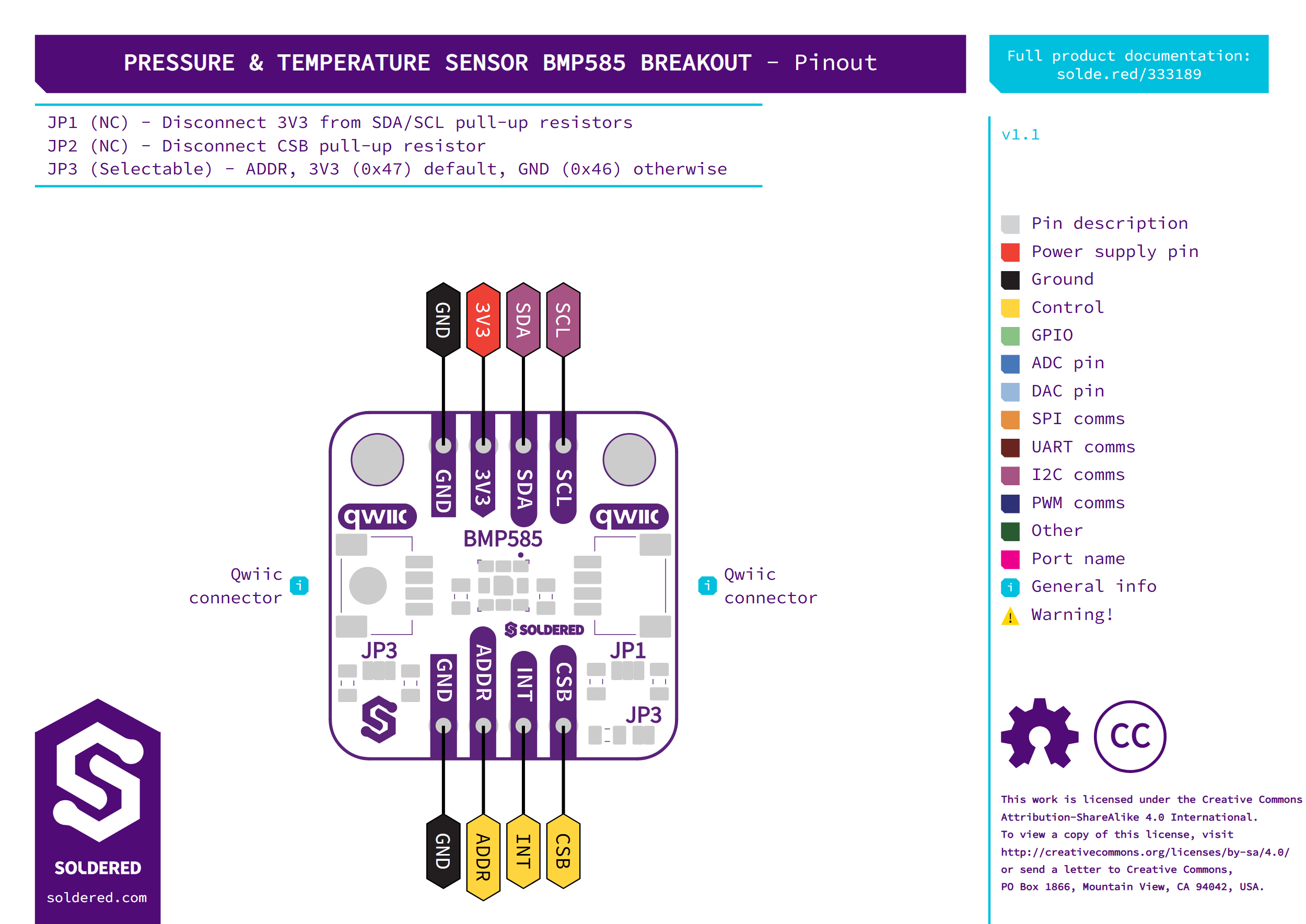
| Pin marking | Pin name | Description |
|---|---|---|
| GND | Ground | Ground. On both headers. |
| 3V3 | Supply | 1.71 to 3.6 V supply for the sensor. Connect it to your controller's 3.3 V pin, never to 5 V. |
| SDA | I2C data | Connect to your controller's I2C data line. Pulled up to 3V3 through 10 kΩ by default. |
| SCL | I2C clock | Connect to your controller's I2C clock line. Pulled up to 3V3 through 10 kΩ by default. |
| ADDR | Address select | The BMP585's address pin: low gives 0x46, high gives 0x47. The address jumper (JP3) pulls it high or low through 10 kΩ. |
| INT | Interrupt output | The BMP585's interrupt pin, for data ready, FIFO and pressure out-of-range events. Its mode, polarity and drive are set in software. |
| CSB | Chip select | Pulled up to 3V3 through 10 kΩ by the CSB jumper (JP2). Held high at power-up, it keeps the sensor on I2C. |
| Qwiic (x2) | Qwiic connectors | Plug-and-play I2C, each carrying 3V3, SDA, SCL and GND. Either works; the other is free for the next Qwiic board. |
Voltage and logic levels
| Connection | Supported voltage | Notes |
|---|---|---|
3V3 supply | 1.71 to 3.6 V | No regulator. The BMP585's core and I/O supplies are both on this pin. |
I2C and signal pins (SDA, SCL, ADDR, INT, CSB) | 3.3 V logic | No level shifter. Do not connect 5 V signals. |
| Qwiic connectors | 3.3 V | Carry 3V3 along with I2C, so a Qwiic cable powers the board. |
Do not connect 5 V to 3V3 or to any signal pin. The BMP585 is rated to 3.6 V,
and the board has no regulator or level shifter to protect it.
Dimensions
The board is 22 x 22 mm, with two mounting holes of 3.2 mm diameter.
Jumpers
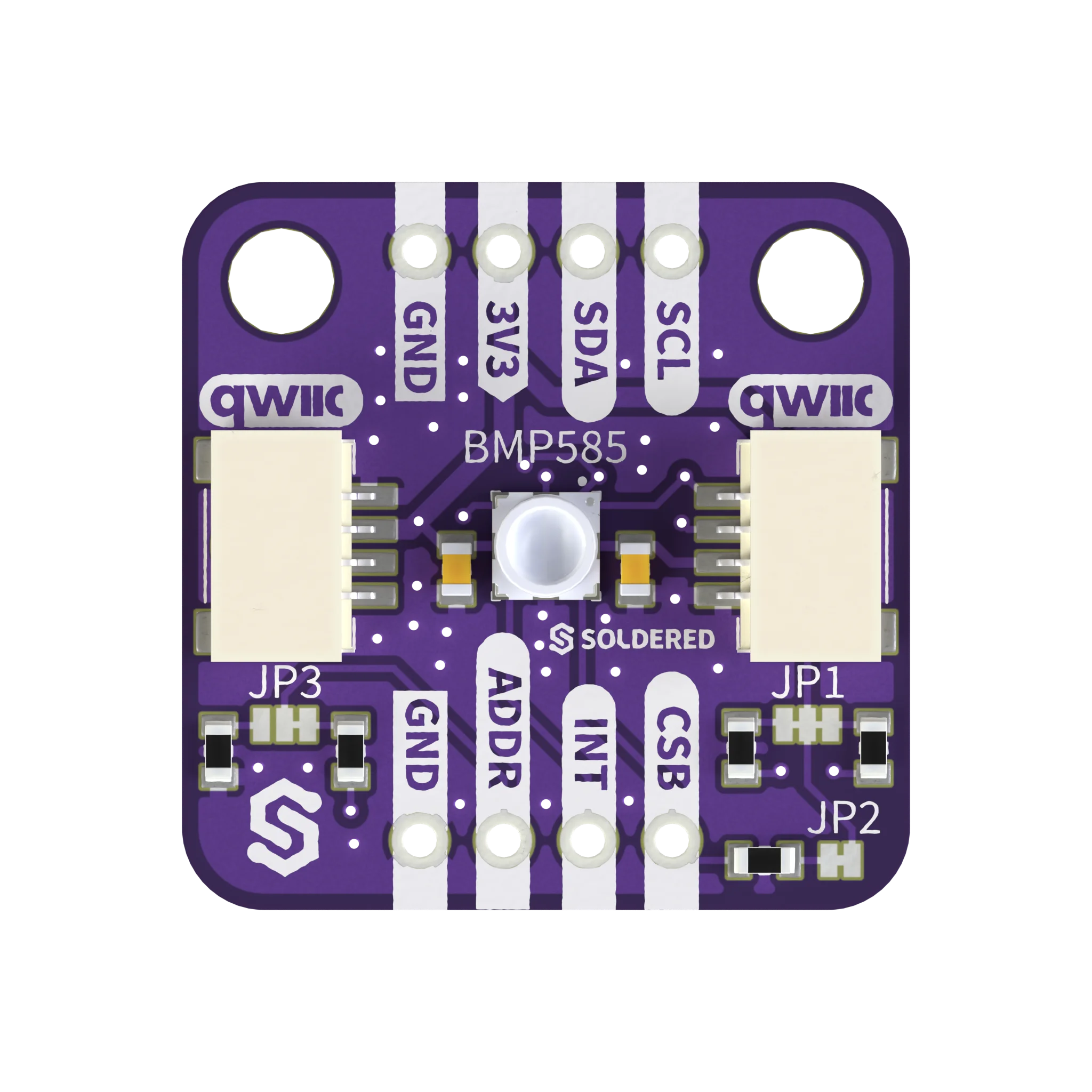
All three jumpers are solder jumpers on the top of the board. With the header
that carries GND, 3V3, SDA and SCL at the top, they sit along the
bottom edge, on either side of the GND, ADDR, INT, CSB header.
| Jumper | Where it is | Default | Function |
|---|---|---|---|
| JP1, I2C pull-ups | 3 pads, bottom right, below the right Qwiic connector | Both sides bridged | Connects a 10 kΩ pull-up from 3V3 to SDA and another to SCL. Cut both bridges to disconnect them. |
| JP2, CSB pull-up | 2 pads, bottom-right corner, below JP1 | Bridged | Pulls CSB up to 3V3 through 10 kΩ, which keeps the sensor on I2C. |
| JP3, address | 3 pads, bottom left, below the left Qwiic connector | Middle pad bridged to the 3V3 side: address 0x47 | Pulls the address pin high or low through 10 kΩ. To use 0x46, cut the default bridge (it joins the middle pad to the 3V3 side) and bridge the middle pad to the other outer pad, the GND side. |
Bridge exactly one side of JP3. With both sides open the
address pin floats, and the BMP585's I2C address is then undefined. With both
sides bridged, 3V3 is tied to GND through two 10 kΩ resistors and the
address pin sits at half the supply, between the BMP585's low and high input
levels, so the address is undefined as well. Keep the
JP2 bridged for I2C unless you drive CSB high yourself: the
datasheet recommends holding CSB high for I2C, and a low CSB turns I2C
off.
No other part on the board uses the bus. Pass the address you chose to
begin() in Arduino or to BMP585() in MicroPython.
Datasheet
The BMP585 datasheet from Bosch Sensortec has the full electrical, timing and register details.