Buttons
The silkscreen on the underside of Inkplate 10 labels three push buttons: a power switch, a reset button and a wake up button. Open the board photo below to find them. This page follows the board version 1.3.1 schematic.
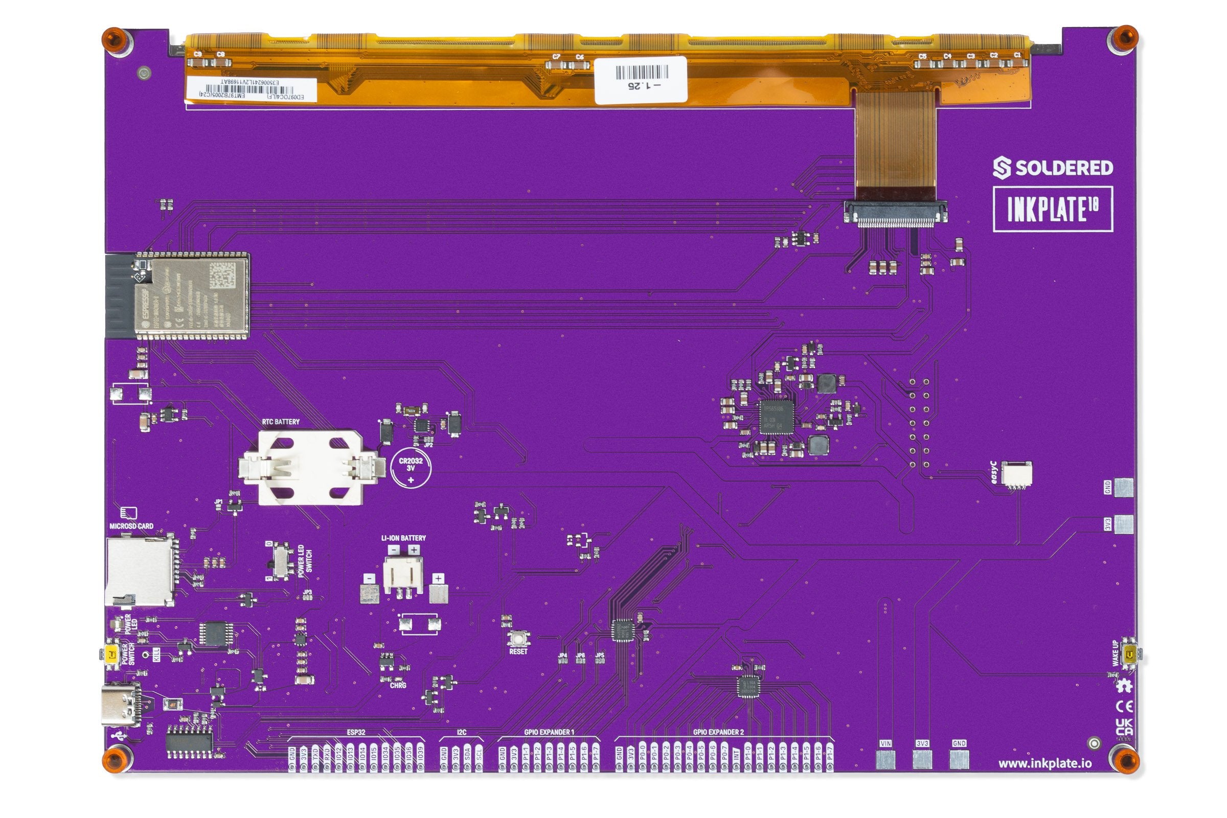
Controls
| Control | Normal action | Notes |
|---|---|---|
WAKE UP | Pulls ESP32 IO36 to GND while pressed. | The Arduino wake button example wakes the board from deep sleep on IO36, active low, with esp_sleep_enable_ext0_wakeup(GPIO_NUM_36, LOW). |
RESET | Restarts the ESP32. | The button feeds the manual reset input of the reset supervisor (a TPS3840 chip) through a 47 Ω resistor. Its reset output goes to the ESP32 EN pin and to both GPIO expanders. |
POWER SWITCH | One press turns the board on or off. | The button feeds a logic circuit (an MC14093B gate) that drives the PMOS transistors in the power path. If you would rather have the board start whenever power is connected, see the bypass page. |
Next to the power switch is a small hole marked KILL. Applying a current to it switches off the power input of Inkplate 10.
For the wake up button in a sketch, see the deep sleep and wake button page in the Arduino section.