Jumpers
Inkplate 10 has six solder jumpers, JP1 to JP6. They change how a few signals are routed: the microSD supply and chip select, the RTC interrupt, and three GPIO expander pins. This page follows the board version 1.3.1 schematic.
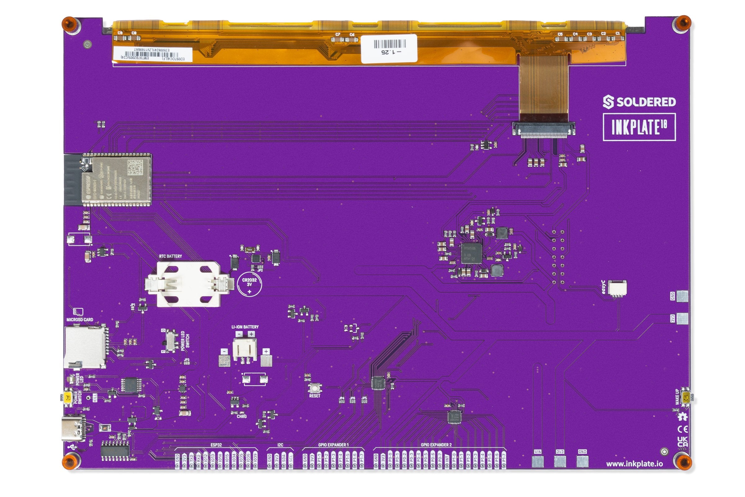
JP2 to JP6 are three-pad jumpers. In the schematic, pads 1 and 2 are joined by a trace by default. To move a signal to the other position, cut that trace and bridge pads 2 and 3 with solder. JP1 has two pads.
| Jumper | Default state | Function |
|---|---|---|
JP1 | Open | Bridge it to connect 3V3 straight to the microSD supply, so the card is powered all the time. This helps when troubleshooting, but it is not a good fit for low-power projects. Open, a PMOS switch (Q10) powers the card. |
JP2 | Pads 1 and 2 joined | Pad 2 goes to ESP32 IO39. Pad 1 is the RTC interrupt output (INT), pad 3 is the RTC clock output (CLKOUT). Default: IO39 reads the RTC interrupt. Moved to pads 2 and 3, IO39 reads the RTC clock output. |
JP3 | Pads 1 and 2 joined | Pad 2 goes to ESP32 IO15. Pad 1 is the microSD chip select, pad 3 goes to the IO15 header pin. Default: IO15 is the microSD chip select. Moved to pads 2 and 3, IO15 is free on the header and the card gets no chip select. |
JP4 | Pads 1 and 2 joined | Pad 2 goes to ESP32 IO34. Pad 1 is the interrupt output of GPIO expander 1, pad 3 goes to the IO34 header pin. Default: IO34 reads the expander 1 interrupt. Moved to pads 2 and 3, IO34 is free on the header. |
JP5 | Pads 1 and 2 joined | Pad 2 goes to expander 1 pin P1-2. Pad 1 drives the gate of the microSD power switch (Q10), pad 3 goes to the P1-2 header pin. Default: P1-2 switches the card power. Moved to pads 2 and 3, P1-2 is free on the header. |
JP6 | Pads 1 and 2 joined | Pad 2 goes to expander 1 pin P1-1. Pad 1 drives the gate of the transistor that switches the battery voltage divider (V_BAT_MOS), pad 3 goes to the P1-1 header pin. Default: P1-1 switches the battery measurement. Moved to pads 2 and 3, P1-1 is free on the header. |
Moving JP3 to pads 2 and 3 disconnects the microSD chip select from the ESP32, so the card stops working until you move it back. Moving JP5 to pads 2 and 3 stops expander 1 from switching the card power. Moving JP6 to pads 2 and 3 stops expander 1 from switching the battery measurement.