Hardware Details
The board holds a vertical USB-C socket and an 8-pin header, and nothing else. There is no chip, no regulator and no resistor between the socket and the pins. Each pin is wired straight to the matching pin of the socket.
Key specifications
| Specification | Value |
|---|---|
| Interface | |
| Interface | USB, USB 2.0 data lines only, no SuperSpeed pairs |
| Qwiic | No |
| Breadboard compatible | Yes, once the header is soldered on |
| Power | |
| Maximum supply voltage | 20 V (connector rating) |
| Current | 5 A (connector rating) |
| Other | |
| Connector | USB-C female, vertical, 16-pin |
| CC resistors | None fitted |
| Header | 8 pins, 2.54 mm pitch, unsoldered |
| Dimensions | 22 × 22 mm |
| Mounting holes | 2 × 3.2 mm |
| In the pack | 3 boards |
Pinout
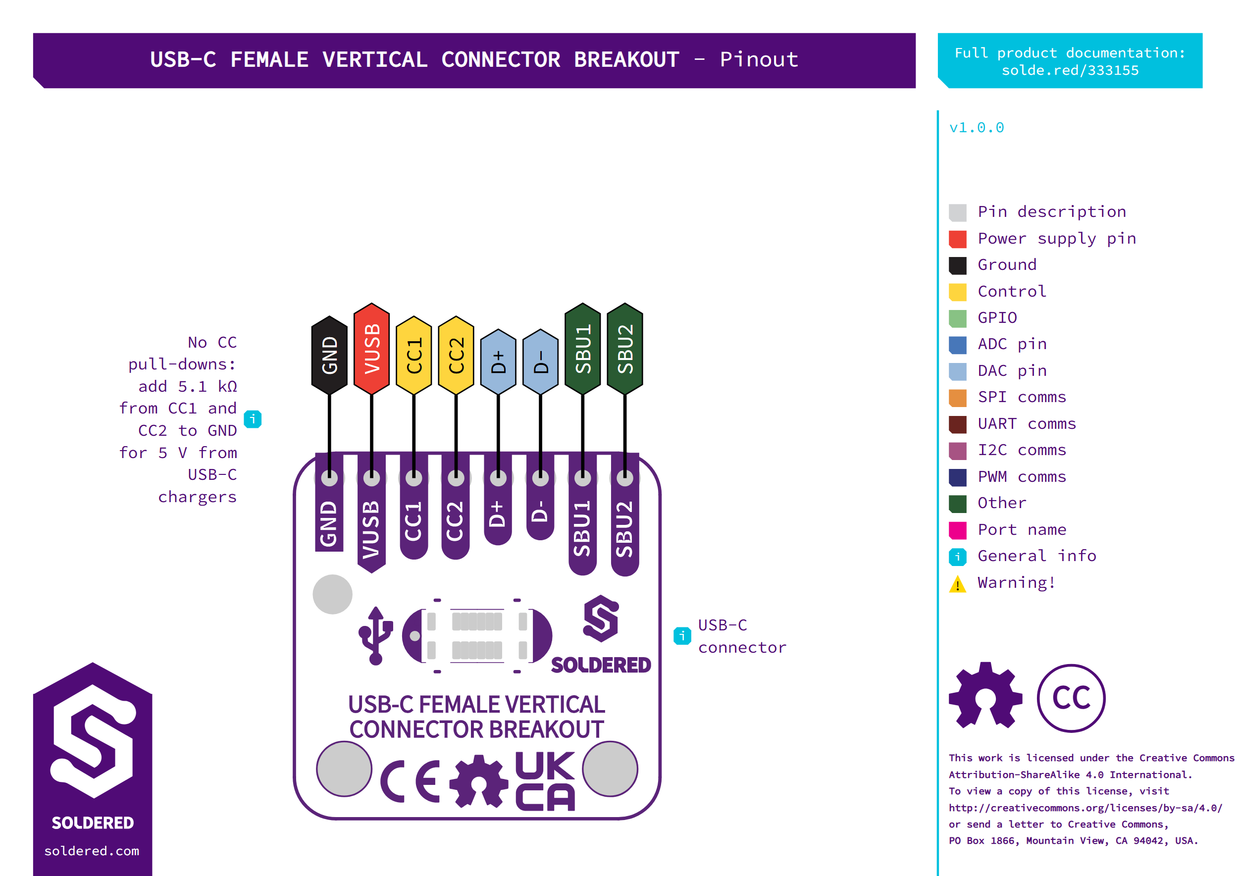
| Pin marking | Pin name | Description |
|---|---|---|
| GND | Ground | Header pin 1. Joined to all the GND pads of the socket and to its shield. |
| VUSB | USB bus voltage | Header pin 2. The 5 V line from the cable, joined to all four VBUS pads of the socket. |
| CC1 | Configuration channel 1 | Header pin 3. A USB-C power source checks the CC lines before it turns the 5 V on. No resistor is fitted. |
| CC2 | Configuration channel 2 | Header pin 4. Works like CC1, on the other side of the socket. No resistor is fitted. |
| D+ | USB 2.0 data plus | Header pin 5. Joined to both D+ pads of the socket. |
| D- | USB 2.0 data minus | Header pin 6. Joined to both D- pads of the socket. |
| SBU1 | Sideband use 1 | Header pin 7. A sideband line that some USB-C modes use. |
| SBU2 | Sideband use 2 | Header pin 8. A sideband line that some USB-C modes use. |
Both D+ pads of the socket are joined, and so are both D- pads. The data lines therefore reach the header with the plug either way up.
Voltage and logic levels
| Connection | Supported voltage | Notes |
|---|---|---|
VUSB | 5 V from the cable | The connector is rated for 20 V. |
CC1, CC2, D+, D-, SBU1, SBU2 | Set by the cable and the device on the other end | The board passes them straight through and does not change them. |
The board has no regulator, level shifter or protection. The voltage you measure on VUSB is the voltage the cable supplies.
Dimensions
The board measures 22 × 22 mm and is 1.6 mm thick. The two 3.2 mm mounting holes sit 16 mm apart, each 3 mm from the nearest side edge and 3 mm from the edge opposite the header. The socket is centred on the board.
The header pins sit 2.54 mm apart, 1.5 mm from the edge nearest the header.