Hardware Details
The Bosch BME280 does the measuring: temperature, relative humidity and barometric pressure, read over I2C at the fixed address 0x76. The board runs the sensor from 3.3 V and gives you two ways in:
- Two Qwiic connectors on the 3.3 V side, wired straight to the sensor.
- A four-pin header on the controller side. An SE5218 regulator turns the header's VCC into 3.3 V for the sensor, and a two-channel MOSFET level shifter translates SDA and SCL between the header and the sensor.
Four solder jumpers set the I2C pull-ups and the power path. This page follows board revision v1.2.0; several product photos show the earlier v1.0.0 board, which is laid out differently and has two mounting holes instead of four.
The board itself has no settings. How often the sensor measures, how much it averages and how long it sleeps between measurements are set in software, and the two Soldered libraries differ: the Arduino library selects normal mode with 16x oversampling on all three measurements, the strongest noise filter and a 1000 ms pause, while the MicroPython module selects normal mode with 1x oversampling, the filter off and the same 1000 ms pause.
Key specifications
| Specification | Value |
|---|---|
| Interface | |
| Interface | I2C |
| Qwiic connectors | 2 |
| Default I2C address | 0x76 |
| Address changeable | No |
| Breadboard compatible | Yes |
| Power | |
| Supply voltage | 3.3 V to 5 V |
| Logic level | 3.3 V or 5 V |
| Current while measuring | 1 mA |
| Current while idle | Under 5 µA |
| Regulator | SE5218, 3.3 V output |
| Other | |
| Sensor IC | BME280 (Bosch) |
| Temperature | -40 to 80 °C, ±1 °C |
| Humidity | 0 to 100 %, ±2 % |
| Pressure | 30 to 110 kPa, ±12 Pa |
| Dimensions | 22 x 38 mm (v1.2.0) |
| Mounting holes | 4 x 3.2 mm |
| Board revision | v1.2.0 |
Pinout
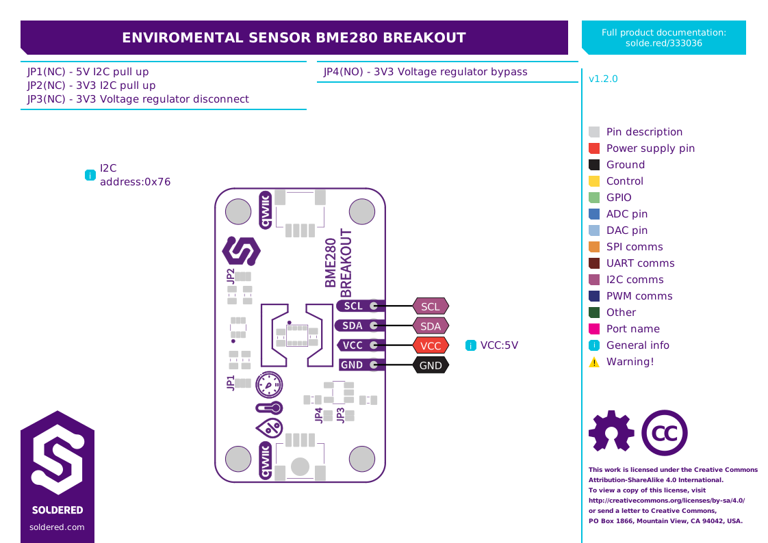
| Pin marking | Pin name | Description |
|---|---|---|
| GND | Ground | Common ground for power and I2C. |
| VCC | Header power | Supply input on the header side, 3.3 V to 5 V. It feeds the on-board regulator, which makes 3.3 V for the sensor. |
| SDA | I2C data, header side | Connect to your controller's I2C data line. The level shifter translates it to the sensor's 3.3 V side. |
| SCL | I2C clock, header side | Connect to your controller's I2C clock line. Translated in the same way as SDA. |
| Qwiic (x2) | Qwiic connectors | 3.3 V power and 3.3 V I2C, wired directly to the sensor. Either connector works, and the other stays free for chaining another Qwiic board. |
Voltage and logic levels
| Connection | Supported voltage | Notes |
|---|---|---|
| Qwiic connectors | 3.3 V | Power and I2C go straight to the sensor's 3.3 V rail, without the regulator or the level shifter. |
| Header VCC | 3.3 V to 5 V | Goes through the SE5218 regulator (JP3) to the 3.3 V rail. |
| Header SDA, SCL | Same as header VCC | A MOSFET level shifter connects them to the sensor's 3.3 V I2C lines. |
You can wire the header to a 3.3 V or a 5 V controller without adding your own level shifter. If you use Qwiic, your controller has to use 3.3 V I2C, which is what Qwiic always carries.
Dimensions
The board measures 22 x 38 mm and has four 3.2 mm mounting holes. Those figures are from the current v1.2.0 design; the earlier v1.0.0 board, which the product photos still show, is 22 x 22 mm with two mounting holes.
Jumpers
| Jumper | Default | Function |
|---|---|---|
| JP1, JP2 | Closed | I2C pull-ups, 10 kΩ on SDA and SCL. JP1 connects the header-side pair to header VCC, JP2 connects the Qwiic-side pair to 3.3 V. Cut a jumper to disconnect its pair, for example when another board on the bus already carries pull-ups. |
| JP3, JP4 | JP3 closed, JP4 open | Power path. JP3 connects header VCC to the 3.3 V regulator's input. JP4 bypasses the regulator and connects header VCC directly to the 3.3 V rail, for powering the board from exactly 3.3 V on the header. |
Closing JP4 ties header VCC straight to the sensor's 3.3 V rail and to the 3.3 V pin of both Qwiic connectors. With JP4 closed, power the header from 3.3 V only, never 5 V. Cut JP3 before you close JP4, so the regulator's input is not connected to its own output.
Hardware repository
The hardware repository for this board is not available yet! We're working on it. In the meantime, please contact us to receive the hardware files.