Bypass Power Switch
Inkplate 10 has a power switch next to the USB-C port, so by default you switch the board on yourself after connecting power. Some builds, such as a wall display, are easier when the board starts as soon as power arrives. This page follows the board version 1.3.1 schematic.
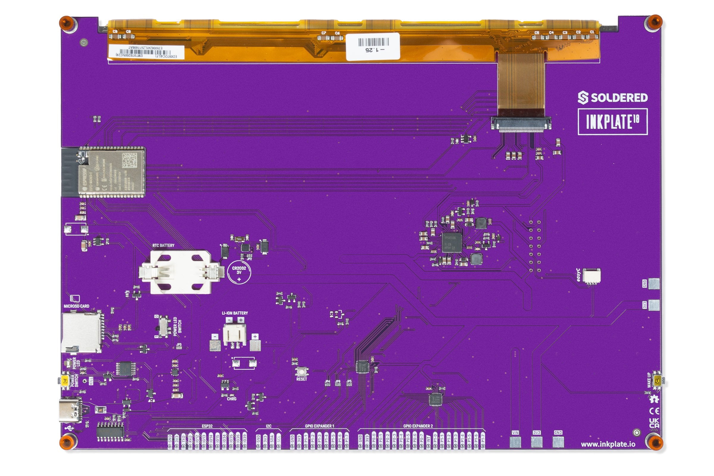
Procedure
The schematic has a 0603 resistor position, R34, that is not fitted on the board (marked DNP, do not populate). It sits between the switched supply (SW_IN) and the board input supply (VIN). Fitting a part there joins the two nets, so the power path is on whenever power is connected.
- Find
R34on the underside of the board. It has no printed label: it is an empty pair of small pads about 3 cm to the right of the power switch, directly below a small three-pin transistor, and about 2 cm below theJP3label. - Bridge its two pads with a small blob of solder, or fit a 0 Ω 0603 resistor.
Bypassing the switch changes the hardware, and the board powers on whenever power is present. You also lose the power switch as a way to turn the board off.