Hardware Details
The board is built around the TXS0104E, a four-channel level translator. The
left header is the low-voltage side and the right header is the high-voltage
side. Each supply has its own 100 nF decoupling capacitor, and a 10 kΩ resistor
pulls OE up to VCCL. There is no voltage regulator: each side runs from the
supply you connect to its VCC pin. The facts on this page come from board
revision V1.2.0.
Key specifications
| Specification | Value |
|---|---|
| Interface | |
| Interface | I2C, digital GPIO |
| Qwiic compatible | No |
| Breadboard compatible | Yes |
| Channels | 4, A1 to A4 paired with B1 to B4 |
| Power | |
| Supply voltage | 1.65 V to 5 V |
| Low-voltage side (VCCL) | 1.65 V to 3.6 V |
| High-voltage side (VCCH) | 2.3 V to 5 V |
| Logic level | 3.3 V or 5 V |
| Other | |
| IC | TXS0104E in a TSSOP-14 package (TXS0104EPWR) |
| Connectors | Two 6-pin 2.54 mm headers and a single OE pin |
| Dimensions | 22 × 22 mm |
| Mounting | Two 3.2 mm holes |
Pinout
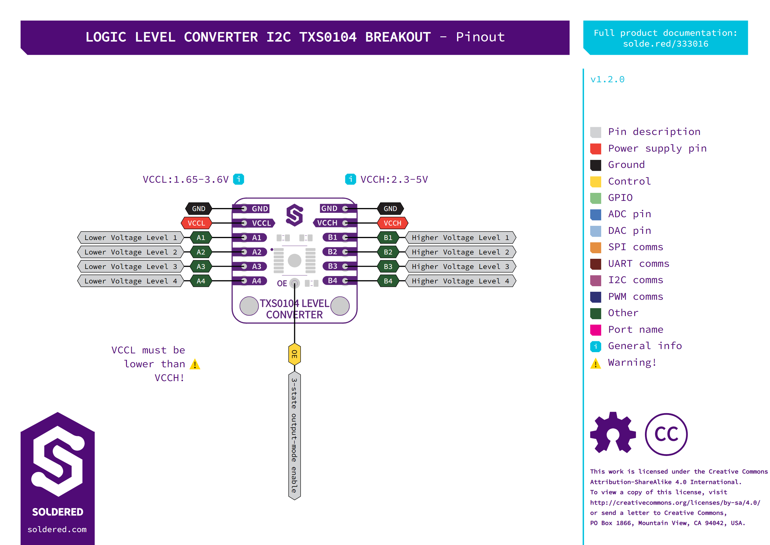
The drawing's warning that VCCL must be lower than VCCH is stricter than
the chip needs: equal supplies, such as 3.3 V on both sides, also work.
Pins are listed top to bottom as drawn above.
| Pin marking | Pin name | Description |
|---|---|---|
GND | Ground | Left header. The same ground as the right header's GND. |
VCCL | Low-voltage supply | Supply for the low-voltage side, 1.65 V to 3.6 V. |
A1 to A4 | Low-voltage signals | Signals at the VCCL level. A1 pairs with B1, and so on. |
GND | Ground | Right header. The same ground as the left header's GND. |
VCCH | High-voltage supply | Supply for the high-voltage side, 2.3 V to 5 V. |
B1 to B4 | High-voltage signals | Signals at the VCCH level. |
OE | Output enable | Single pin below the chip. Pulled up to VCCL through 10 kΩ, so the outputs are on when it is left unconnected. Pull it low to put all outputs into the 3-state (high-impedance) mode. |
Voltage and logic levels
| Connection | Supported voltage | Notes |
|---|---|---|
VCCL, A1 to A4 | 1.65 V to 3.6 V | The lower-voltage side, for example a 3.3 V sensor. |
VCCH, B1 to B4 | 2.3 V to 5 V | The higher-voltage side, for example a 5 V controller. |
OE | VCCL level | Pulled up to VCCL on the board. |
VCCL must never be higher than VCCH, and equal supplies are fine. Connect
the ground of both systems: the two GND pins are joined on the board and
give the signals a common reference.
Dimensions
The board is 22 × 22 mm, with two 3.2 mm mounting holes 16 mm apart. Both 6-pin headers use a 2.54 mm pitch with 1.0 mm holes, and the two header rows are 17.78 mm (0.7 in) apart.
Jumpers
The board has no solder jumpers.