Hardware Details
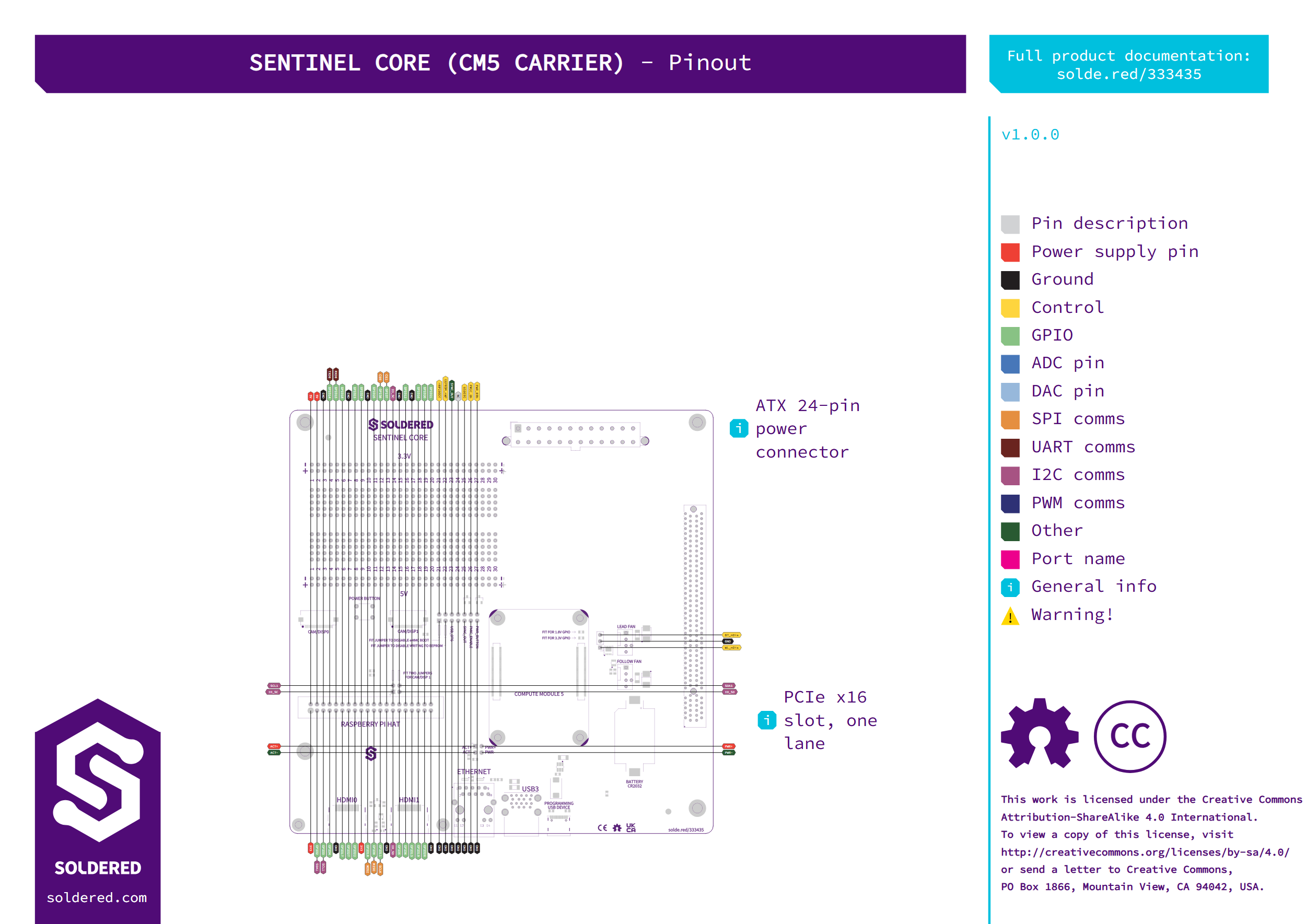
Sentinel Core carries a Raspberry Pi Compute Module 5 (CM5 or CM5 Lite, not included) on two 100-pin board-to-board connectors, in the area marked COMPUTE MODULE 5.
Key specifications
| Specification | Value |
|---|---|
| Interface | |
| Module connectors | 2x 100-pin board-to-board, for Compute Module 5 or CM5 Lite |
| Expansion | PCIe x16 slot, one lane, PCIe Gen 2 from the module |
| Video | 2x HDMI 2.0, full-size connectors |
| USB | 2x USB 3.0 Type-A (stacked) with a current-limited power switch; USB 2.0 on the USB-C port |
| Network | Gigabit Ethernet RJ45 with integrated magnetics and ESD protection |
| Camera and display | 2x 22-pin MIPI connectors (CSI or DSI) |
| GPIO | 40-pin header with the Raspberry Pi pinout |
| Fans | 2x 4-pin 12 V PWM fan headers, tachometer on one |
| Power | |
| Power input | 24-pin ATX connector, or USB-C at 5 V (the module negotiates up to 5 A over USB PD) |
| Input isolation | Ideal-diode circuit between the ATX and USB-C inputs |
| 12 V | From the ATX input only, for the PCIe slot and the fan headers |
| GPIO logic level | 3.3 V by default, 1.8 V selectable with a 0 Ω resistor |
| Other | |
| Form factor | Mini-ITX, 170 x 170 mm |
| RTC | CR2032 battery holder for the module's real-time clock |
| Controls | Power button, 14-pin service header |
| Indicators | Power LED (red) and activity LED (green); 2 x 2 front-panel header for a case's power and activity LEDs |
Power
The board runs from either of two inputs:
- 24-pin ATX connector. A standard ATX power supply feeds the board's 5 V, and its 12 V and 3.3 V rails feed the PCIe slot. Its 12 V also feeds both fan headers.
- USB-C port at 5 V. The module negotiates up to 5 A over USB PD on this port.
An ideal-diode circuit keeps the two inputs apart, so the USB-C supply never feeds back into the ATX supply. The PCIe slot and the fan headers take their 12 V only from the ATX supply: on USB-C power alone, a PCIe card and the fans get no 12 V.
Dimensions
The board is 170 x 170 mm, the Mini-ITX size, so it mounts in a standard Mini-ITX case.
Connections
| Marking or part | What it is |
|---|---|
COMPUTE MODULE 5 | Two 100-pin connectors for the Compute Module 5 or CM5 Lite |
| PCIe slot | PCIe x16 slot wired to the module's single PCIe Gen 2 lane |
HDMI0, HDMI1 | Full-size HDMI 2.0 ports |
USB3 | Two stacked USB 3.0 Type-A ports, powered through a current-limited switch |
PROGRAMMING USB DEVICE | USB-C port: 5 V power input and the module's USB 2.0 port |
ETHERNET | Gigabit Ethernet RJ45 jack with integrated magnetics, no Power over Ethernet |
CAM/DISP0, CAM/DISP1 | 22-pin MIPI connectors for a CSI camera or a DSI display |
RASPBERRY PI HAT | 40-pin GPIO header with the Raspberry Pi pinout |
LEAD FAN, FOLLOW FAN | 4-pin 12 V PWM fan headers. Both share one PWM signal, and one of them has its tachometer line connected |
BATTERY CR2032 | Coin-cell holder for the module's real-time clock |
POWER BUTTON | The board's power button |
ACT+, ACT-, PWR+, PWR- | Front-panel header for a case's activity and power LEDs |
| 24-pin power connector | ATX power input |
CAM/DISP1 jumpers
CAM/DISP1 needs two jumpers on the 2 x 2 header marked FIT TWO JUMPERS FOR CAM/DISP 1. They connect the module's ID_SC and ID_SD lines to the I2C lines of the CAM/DISP1 connector. CAM/DISP0 needs no jumpers.
Service header
The 14-pin (2 x 7) service header carries the module's control lines. Every odd pin is GND, so each function is a pair of pins you can short with a jumper or wire to a switch.
| Pins | Silkscreen | Function |
|---|---|---|
| 1 and 2 | FIT JUMPER TO DISABLE eMMC BOOT | A jumper forces rpiboot mode, for flashing the module's eMMC over the USB-C port |
| 3 and 4 | FIT JUMPER TO DISABLE WRITING TO EEPROM | A jumper write-protects the module's EEPROM |
| 5 and 6 | SYNC_OUT | The module's sync output |
| 7 and 8 | none | Pin 8 is not connected |
| 9 and 10 | USB_OTG | The module's USB OTG line |
| 11 and 12 | PMIC_ENABLE | The module's PMIC enable line |
| 13 and 14 | PWR_BUTTON | The power-button line, the same one the POWER BUTTON switch pulls to GND. Wire a case's power switch here |
GPIO logic level
GPIO signalling is 3.3 V by default. A 0 Ω resistor next to the module connectors selects it: the board ships with the resistor on the pads marked FIT FOR 3.3V GPIO. For 1.8 V signalling, move it to the pads marked FIT FOR 1.8V GPIO.
Fit a resistor on only one of the two positions. Both connect to the same GPIO reference line, so fitting both joins the 3.3 V and 1.8 V supplies.