Quick Start
This board measures the magnetic field on three axes. Connect it over I2C, install the library for your environment, and run its basic readings example to see the X, Y and Z field in microtesla (µT) and the sensor's temperature.
You program the controller connected to this breakout. The breakout itself is not flashed.
- Arduino
- MicroPython
1. Connect the breakout board
Plug a Qwiic cable into either Qwiic connector on the breakout and into the Qwiic connector on your controller. The one cable carries power and I2C.
| NULA DeepSleep | Soldered 3-axis Magnetometer BMM350 Breakout |
|---|---|
| Qwiic connector | Qwiic connector |
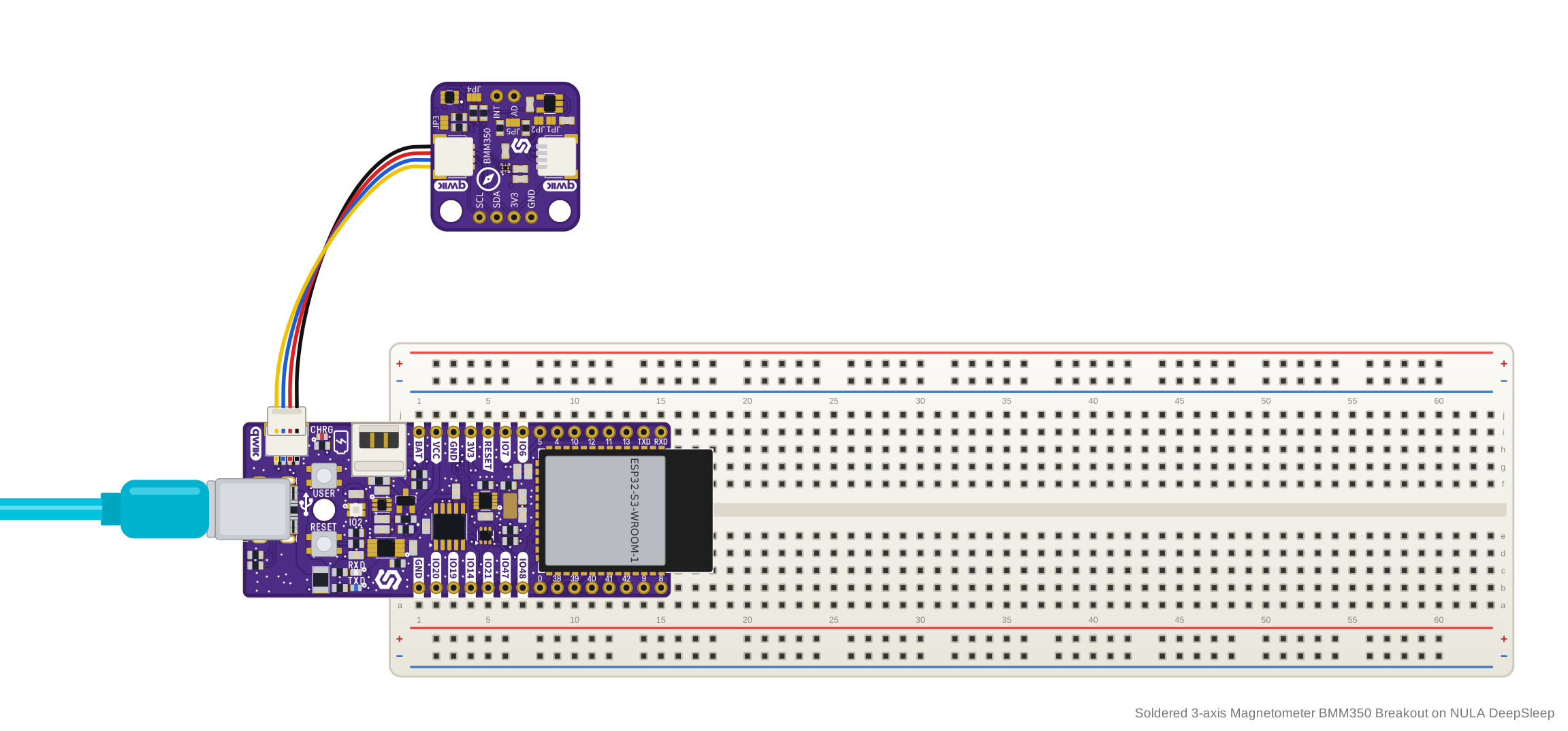
Without Qwiic: breadboard wiring
Solder the included header pins and wire the 4-pin header to your controller's power and I2C pins:
| NULA DeepSleep | Soldered 3-axis Magnetometer BMM350 Breakout |
|---|---|
| GND | GND |
| 3V3 | 3V3 |
| IO8 | SDA |
| IO9 | SCL |
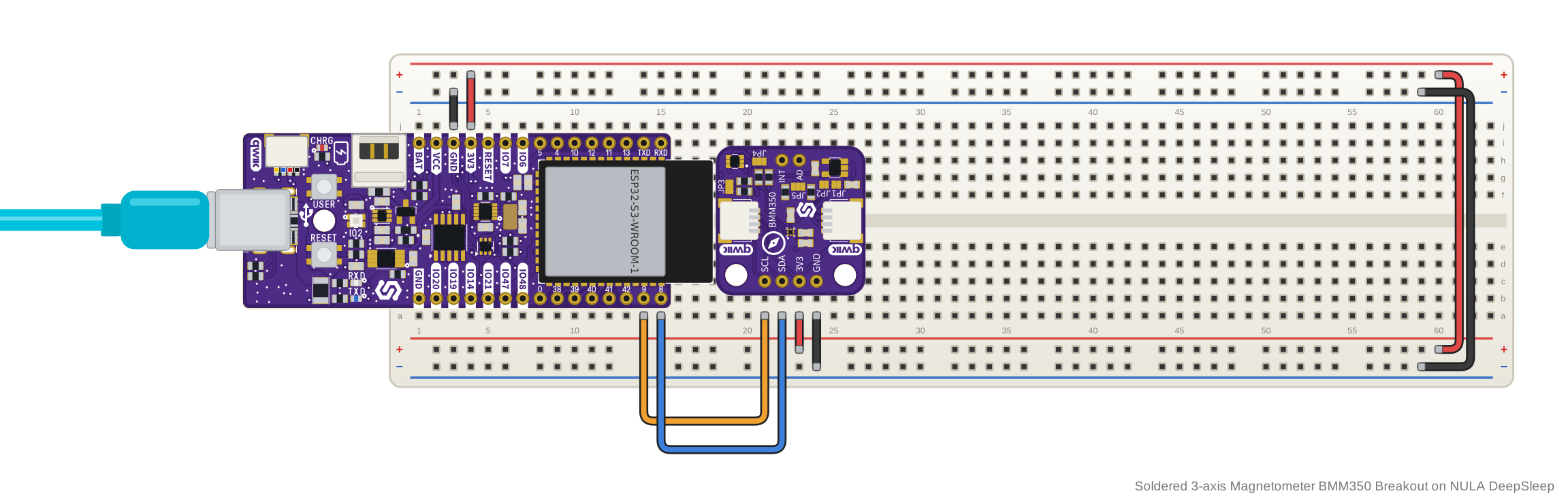
The header side works from 2 V to 5 V, through the board's 1.8 V regulator and I2C level shifter. The Qwiic connectors share the same supply, so if you power the header from 5 V, both Qwiic connectors carry 5 V too.
2. Install the library
Download the Soldered BMM350 Geomagnetic Sensor library from its GitHub repository and add it to the Arduino IDE as a ZIP library.
🔗Soldered BMM350 Geomagnetic Sensor
Verified Arduino library at commit 8ef2cae
Tip: downloading from GitHub. On the library's GitHub page, click the green Code button and choose Download ZIP, then add it in Arduino IDE with Sketch → Include Library → Add .ZIP Library....
3. Run the first example
This is basicReadings.ino, the library's simplest example. It starts the
sensor at the default address 0x14 and prints the field on all three axes in
µT and the temperature in °C, about 10 times a second. Upload it, then open the
Serial Monitor at 115200 baud.
/**
 **************************************************
 *
 * @file        basicReadings.ino
 *
 * @brief       Example showing how to read compensated magnetometer and
 *              temperature data from the Soldered BMM350 Geomagnetic
 *              Sensor breakout over I2C
 *
 * @link        solde.red/333359 : Soldered BMM350 Geomagnetic Sensor breakout
 *
 * @authors     Soldered Electronics
 ***************************************************/
#include <BMM350-SOLDERED.h>

// Create an instance of the BMM350 sensor
Soldered_BMM350 magSensor;

void setup()
{
    // Initialize serial for output
    Serial.begin(115200);
    Serial.println("BMM350 Example - Basic Readings");

    // Initialize I2C bus
    Wire.begin();

    // Check if sensor is connected and initialize it.
    // Address is optional, defaults to 0x14 (ADSEL tied low on this breakout)
    while (magSensor.begin() != BMM350_OK)
    {
        Serial.println("Error: BMM350 not connected, check wiring and I2C address!");
        delay(1000);
    }

    Serial.println("BMM350 connected!");
}

void loop()
{
    // Get new measurements from the sensor. This must be called before
    // accessing the magX/magY/magZ/temperature data, otherwise it will never update
    if (magSensor.getSensorData() == BMM350_OK)
    {
        Serial.print("X: ");
        Serial.print(magSensor.magX, 2);
        Serial.print(" uT\t");
        Serial.print("Y: ");
        Serial.print(magSensor.magY, 2);
        Serial.print(" uT\t");
        Serial.print("Z: ");
        Serial.print(magSensor.magZ, 2);
        Serial.print(" uT\t");
        Serial.print("Temperature: ");
        Serial.print(magSensor.temperature, 2);
        Serial.println(" degC");
    }

    // Print 10x per second
    delay(100);
}
4. Check the result
Once the sensor answers, the Serial Monitor shows the two start lines, then one
line per reading, about every 100 ms: the field on X:, Y: and Z: in uT
with two decimals, then Temperature: in degC, separated by tabs.
BMM350 Example - Basic Readings
BMM350 connected!
X: 12.84 uT	Y: -21.37 uT	Z: -38.92 uT	Temperature: 24.61 degC
X: 12.79 uT	Y: -21.42 uT	Z: -38.88 uT	Temperature: 24.62 degC
X: 12.86 uT	Y: -21.35 uT	Z: -38.95 uT	Temperature: 24.62 degC
X: 12.81 uT	Y: -21.40 uT	Z: -38.90 uT	Temperature: 24.63 degC
If you see Error: BMM350 not connected, check wiring and I2C address! once a
second instead, the sensor did not answer at 0x14.
5. If it does not work
Continue with Troubleshooting and retry this smallest example after each change.
1. Connect the breakout board
Plug a Qwiic cable into either Qwiic connector on the breakout and into the Qwiic connector on your controller. The one cable carries power and I2C.
| NULA DeepSleep | Soldered 3-axis Magnetometer BMM350 Breakout |
|---|---|
| Qwiic connector | Qwiic connector |
Without Qwiic: breadboard wiring
Solder the included header pins and wire the 4-pin header to your controller. The example below uses I2C bus 0 with SDA on GPIO 8 and SCL on GPIO 9; wire those pins, or change them in the example to the pins you use.
| NULA DeepSleep | Soldered 3-axis Magnetometer BMM350 Breakout |
|---|---|
| GND | GND |
| 3V3 | 3V3 |
| IO8 | SDA |
| IO9 | SCL |
The header side works from 2 V to 5 V, through the board's 1.8 V regulator and I2C level shifter. The Qwiic connectors share the same supply, so if you power the header from 5 V, both Qwiic connectors carry 5 V too.
2. Install the module
Use mim, or, after installing the mpremote package, install the library on your board using the following command:
mpremote mip install github:SolderedElectronics/Soldered-BMM350-MicroPython-Library
Or, if you're running a Windows OS:
python -m mpremote mip install github:SolderedElectronics/Soldered-BMM350-MicroPython-Library
🔗Soldered BMM350 MicroPython library
Verified MicroPython module at commit 0995e8d
Tip: downloading from GitHub. Without mpremote, open the module's .py
file on GitHub and click Download raw file, then open it in Thonny and use
File → Save as... → MicroPython device to copy it onto the board.
3. Run the first example
This is bmm350-basicReadings.py. It creates the I2C bus, starts the sensor at
the default address 0x14 and prints the field on all three axes in µT and the
temperature in °C, about every 100 ms. Change the scl and sda pins on the
I2C(...) line to the pins you wired, then run it on your board.
# FILE: bmm350-basicReadings.py
# AUTHOR: Soldered Electronics
# BRIEF: Reads compensated magnetometer and temperature data from the BMM350
#        sensor over I2C
# WORKS WITH: BMM350 Geomagnetic Sensor breakout: www.solde.red/333359
# LAST UPDATED: 2026-09-22

from bmm350 import BMM350, BMM350_OK
from machine import I2C, Pin
import time

# Change these to match how your board wires I2C
i2c = I2C(0, scl=Pin(9), sda=Pin(8))
sensor = BMM350(i2c)

if sensor.status != BMM350_OK:
    raise Exception("Failed to initialize BMM350: " + sensor.status_string())

print("BMM350 connected!")

while True:
    if sensor.get_sensor_data() == BMM350_OK:
        print(
            "X: {:.2f} uT\tY: {:.2f} uT\tZ: {:.2f} uT\tTemperature: {:.2f} degC".format(
                sensor.data.mag_x, sensor.data.mag_y, sensor.data.mag_z, sensor.data.temperature
            )
        )
    else:
        print("Failed to read sensor data:", sensor.status_string())

    time.sleep_ms(100)
🔗Open the complete example
bmm350-basicReadings.py at commit 0995e8d
4. Check the result
Once the sensor answers, the shell shows BMM350 connected!, then one line per
reading, about every 100 ms: the field on X:, Y: and Z: in uT with two
decimals, then Temperature: in degC, separated by tabs.
BMM350 connected!
X: 12.47 uT	Y: -8.31 uT	Z: -37.92 uT	Temperature: 24.58 degC
X: 12.52 uT	Y: -8.28 uT	Z: -37.85 uT	Temperature: 24.58 degC
X: 12.44 uT	Y: -8.35 uT	Z: -37.96 uT	Temperature: 24.61 degC
X: 12.50 uT	Y: -8.29 uT	Z: -37.89 uT	Temperature: 24.61 degC
If a read fails, the line reads Failed to read sensor data: and the reason
instead.
If the sensor does not answer, the script stops with an exception that names
the address it tried, for example BMM350 not responding on address 0x14.
5. If it does not work
Continue with Troubleshooting and retry this smallest example after each change.