Hardware Details
The board pairs an Aerobits TT-SC1 1090 MHz ADS-B receiver with an ESP32-S3-WROOM-1-N8R8 module. The TT-SC1 talks to the ESP32-S3 over UART, so the two 12-pin headers break out the receiver's UART, SPI, I2C, reset and boot lines next to the free ESP32-S3 pins. Two Qwiic connectors carry the ESP32-S3's I2C bus (GND, 3.3 V, SDA, SCL) so a display or sensor can be added without soldering.
Pinout
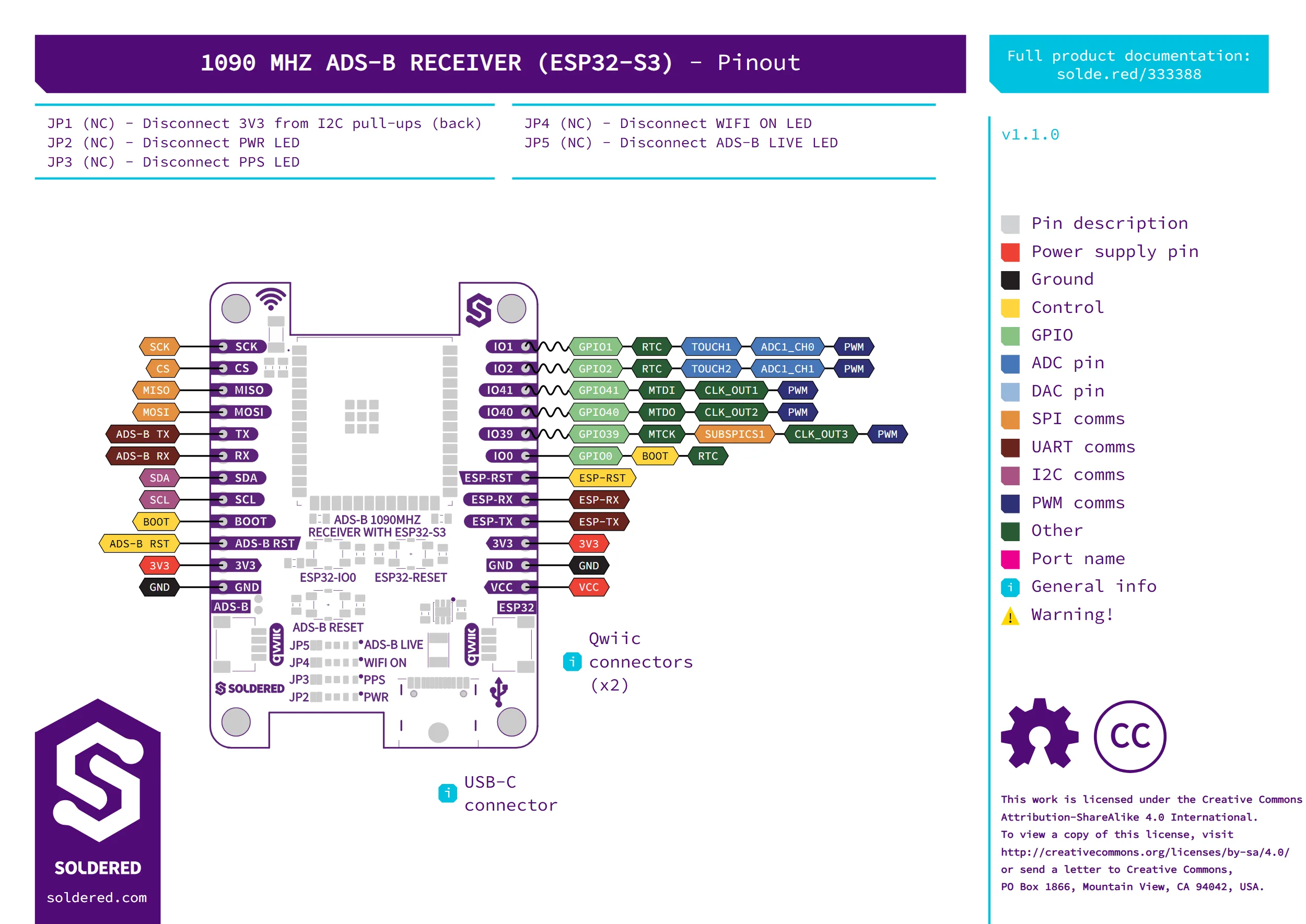
Pin details
| Pin marking | Pin name | Description |
|---|---|---|
| SCK | TT-SC1 SPI clock | Reserved for future use on the TT-SC1 receiver. |
| CS | TT-SC1 SPI chip select | Reserved for future use on the TT-SC1 receiver. |
| MISO | TT-SC1 SPI data out | Reserved for future use on the TT-SC1 receiver. |
| MOSI | TT-SC1 SPI data in | Reserved for future use on the TT-SC1 receiver. |
| ADS-B TX | TT-SC1 main UART TX | Decoded ADS-B data leaves the receiver here. Also wired internally to the ESP32-S3's GPIO17 (its UART1 RX). |
| ADS-B RX | TT-SC1 main UART RX | Commands and configuration go into the receiver here. Also wired internally to the ESP32-S3's GPIO18 (its UART1 TX). |
| SDA | TT-SC1 I2C data | Reserved for future use on the TT-SC1 receiver. |
| SCL | TT-SC1 I2C clock | Reserved for future use on the TT-SC1 receiver. |
| BOOT | TT-SC1 bootloader/configuration trigger | Drives the receiver's B/C pin, used to enter its CONFIGURATION or BOOTLOADER state. |
| ADS-B RST | TT-SC1 reset | Resets the receiver module. Also wired internally to the ESP32-S3's GPIO21, so firmware can trigger this reset without a jumper wire. |
| IO1 | ESP32-S3 GPIO1 | RTC_GPIO1, TOUCH1, ADC1_CH0. |
| IO2 | ESP32-S3 GPIO2 | RTC_GPIO2, TOUCH2, ADC1_CH1. |
| IO41 | ESP32-S3 GPIO41 | MTDI (JTAG), CLK_OUT1. |
| IO40 | ESP32-S3 GPIO40 | MTDO (JTAG), CLK_OUT2. |
| IO39 | ESP32-S3 GPIO39 | MTCK (JTAG), SUBSPICS1, CLK_OUT3. |
| IO0 | ESP32-S3 GPIO0 | RTC_GPIO0. Also the chip's own boot-mode strapping pin. |
| ESP-RST | ESP32-S3 EN (reset) | Resets the ESP32-S3 module. |
| ESP-RX | ESP32-S3 UART0 RX | Shared with the CH340K USB-serial bridge. |
| ESP-TX | ESP32-S3 UART0 TX | Shared with the CH340K USB-serial bridge. |
| VCC | Board power input | 5 V, the same rail as the USB-C connector. |
| 3V3 | 3.3 V rail | Regulated output of the onboard TPS7A2633. |
| GND | Ground | Common ground. |
Separate reset buttons on the board reset the ESP32-S3 and the TT-SC1 receiver independently, so you can restart one without power-cycling the other.
Power supply
The board takes 5 V from the USB-C connector or the header's VCC pin. An onboard TPS7A2633 regulator steps this down to a 3.3 V rail (500 mA max) that powers the ESP32-S3, the TT-SC1 receiver, and both Qwiic connectors. All I/O runs at 3.3 V logic.
The TT-SC1 receiver itself draws about 70 mA typical at 3.3 V and has no sleep mode, so the board's own current draw does not drop much below that even when the ESP32-S3 is idle.
Dimensions
- Board size: 38 x 54 mm
- Mounting: four 3.2 mm holes
Jumpers
| Jumper | Default | Function |
|---|---|---|
| JP1 | Closed | Cut to disconnect the 3.3 V I2C pull-ups (on the back of the board). |
| JP2 | Closed | Cut to disconnect the power (PWR) status LED. |
| JP3 | Closed | Cut to disconnect the PPS status LED. |
| JP4 | Closed | Cut to disconnect the Wi-Fi-on status LED. |
| JP5 | Closed | Cut to disconnect the ADS-B-live status LED. |