Hardware Details
The board carries a Bosch BME690, which measures temperature, relative humidity,
barometric pressure and the resistance of a heated metal-oxide gas sensor. It
talks I2C only, through two Qwiic connectors and a 4-pin header that share the
same four lines. Two 100 nF capacitors decouple the sensor, 10 kΩ pull-ups sit
on SDA and SCL, and two solder jumpers set the I2C address and disconnect
the pull-ups.
Key specifications
| Specification | Value |
|---|---|
| Interface | |
| Interface | I2C |
| Qwiic compatible | Yes, 2 connectors |
| Default I2C address | 0x76 |
| I2C address changeable | Yes, 0x77 with the ADDR jumper |
| Breadboard compatible | Yes, 4-pin 2.54 mm header (GND, 3V3, SDA, SCL) |
| Power | |
| Supply voltage | 1.71 to 3.6 V on 3V3, no regulator |
| Logic level | 3.3 V only |
| Operating current | 3.1 mA average in standard gas scan mode (Bosch figure at 1.8 V) |
| Sleep current | 0.11 µA (Bosch figure at 1.8 V, 25 °C) |
| Pull-ups | 10 kΩ on SDA and SCL, disconnect with the jumper |
| Other | |
| Sensor | Bosch BME690 |
| Measures | Temperature, relative humidity, pressure, gas resistance |
| Temperature | -40 to 85 °C, ±0.5 °C (0 to 65 °C), ±1 °C outside that range |
| Humidity | 0 to 100 % r.H., ±3 % r.H. (20 to 80 % r.H., 25 °C, including hysteresis) |
| Pressure | 300 to 1100 hPa, ±0.5 hPa (0 to 65 °C) |
| Gas scan | 10.8 s per standard scan (Bosch figure) |
| Mounting holes | 2x 3.2 mm |
| Dimensions | 22 x 22 mm |
Pinout
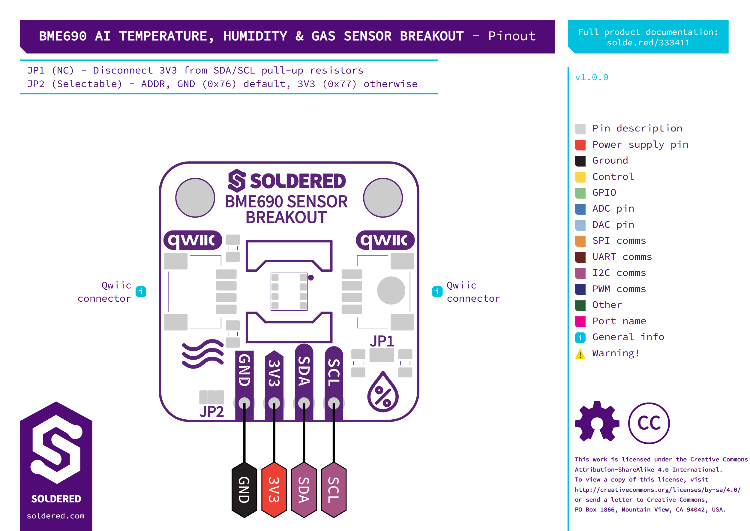
| Pin marking | Pin name | Description |
|---|---|---|
GND | Ground | Common ground with the controller. |
3V3 | Supply | 1.71 to 3.6 V. Feeds the sensor's VDD and VDDIO directly, so it also sets the I2C logic level. |
SDA | I2C data | Sensor data line, with a 10 kΩ pull-up to 3V3 while the pull-up jumper is closed. |
SCL | I2C clock | Sensor clock line, with a 10 kΩ pull-up to 3V3 while the pull-up jumper is closed. |
| Qwiic (2x) | 3V3, GND, SDA, SCL | The same four lines as the header. Use either connector, and the other one to chain the next Qwiic board. |
Voltage and logic levels
| Connection | Supported voltage | Notes |
|---|---|---|
3V3 | 1.71 to 3.6 V | No regulator on the board. 4.25 V is the sensor's absolute maximum. |
SDA, SCL | Up to the 3V3 supply | The sensor's I/O runs from 3V3. Its absolute maximum on an interface pin is the supply plus 0.3 V. |
| Qwiic | 3.3 V | Carries the same 3V3, GND, SDA and SCL. |
This is a 3.3 V board. Do not connect 3V3 to 5 V, and do not pull SDA
or SCL above the 3V3 supply, for example from a 5 V controller.
Dimensions
The board measures 22 x 22 mm and has two 3.2 mm mounting holes. Their centres are 16 mm apart, and each centre is 3 mm from the two nearest board edges.
Jumpers
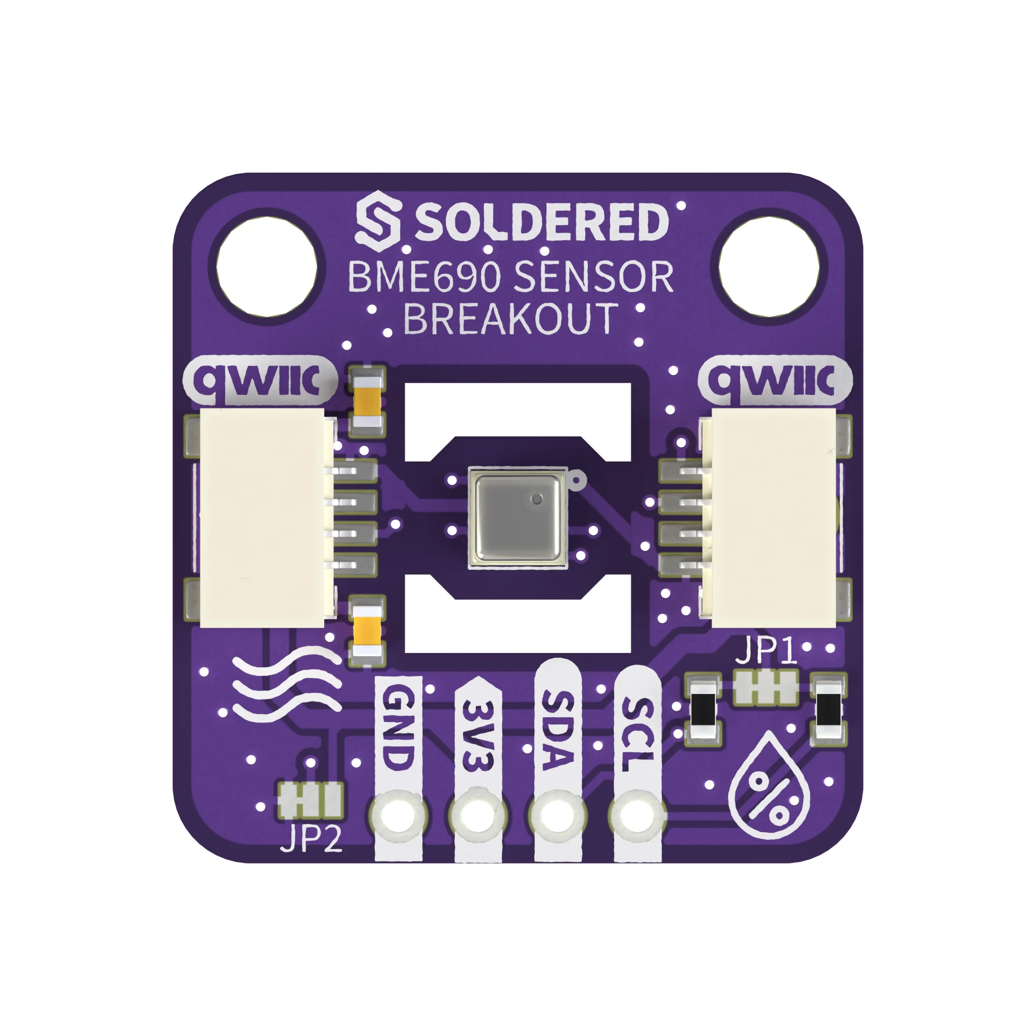
| Jumper | Default | Function |
|---|---|---|
JP2 (ADDR) | 0x76: a copper trace joins the middle pad to the GND pad, so the sensor's SDO is on GND | Sets the I2C address. For 0x77, cut the trace between the middle pad and the GND pad, then solder the middle pad to the 3V3 pad, and create the sensor with BME690(address=BME69X_I2C_ADDR_HIGH). |
JP1 | Connected: copper traces join the middle pad (3V3) to both side pads | Connects the 10 kΩ pull-ups on SDA and SCL to 3V3. Cut both traces to remove the pull-ups, for example when other boards on the bus already provide them. |
Join the middle pad of JP2 to exactly one side. Joined to both the GND
and the 3V3 pad, it shorts 3V3 to GND: cut the trace to the GND pad
before you solder the 3V3 side. Joined to neither, the sensor's SDO pin
floats and its I2C address is undefined.