Hardware Details
The Bosch BMV080 does the measuring. It reports PM1, PM2.5 and PM10 mass concentration from particles that drift through a sensing region about 5 mm above its lens, with no fan pulling air in. The board powers it straight from 3.3 V and brings its interface out in two ways:
- Two Qwiic connectors with 3.3 V, GND, SDA and SCL, for a cable to your controller and a second one to chain another Qwiic board.
- A 7-pin header with power, the I2C lines, both address pins and the interrupt output. In SPI mode the same pins carry SPI.
Four solder jumpers choose I2C or SPI, set the I2C address and connect the I2C pull-up resistors.
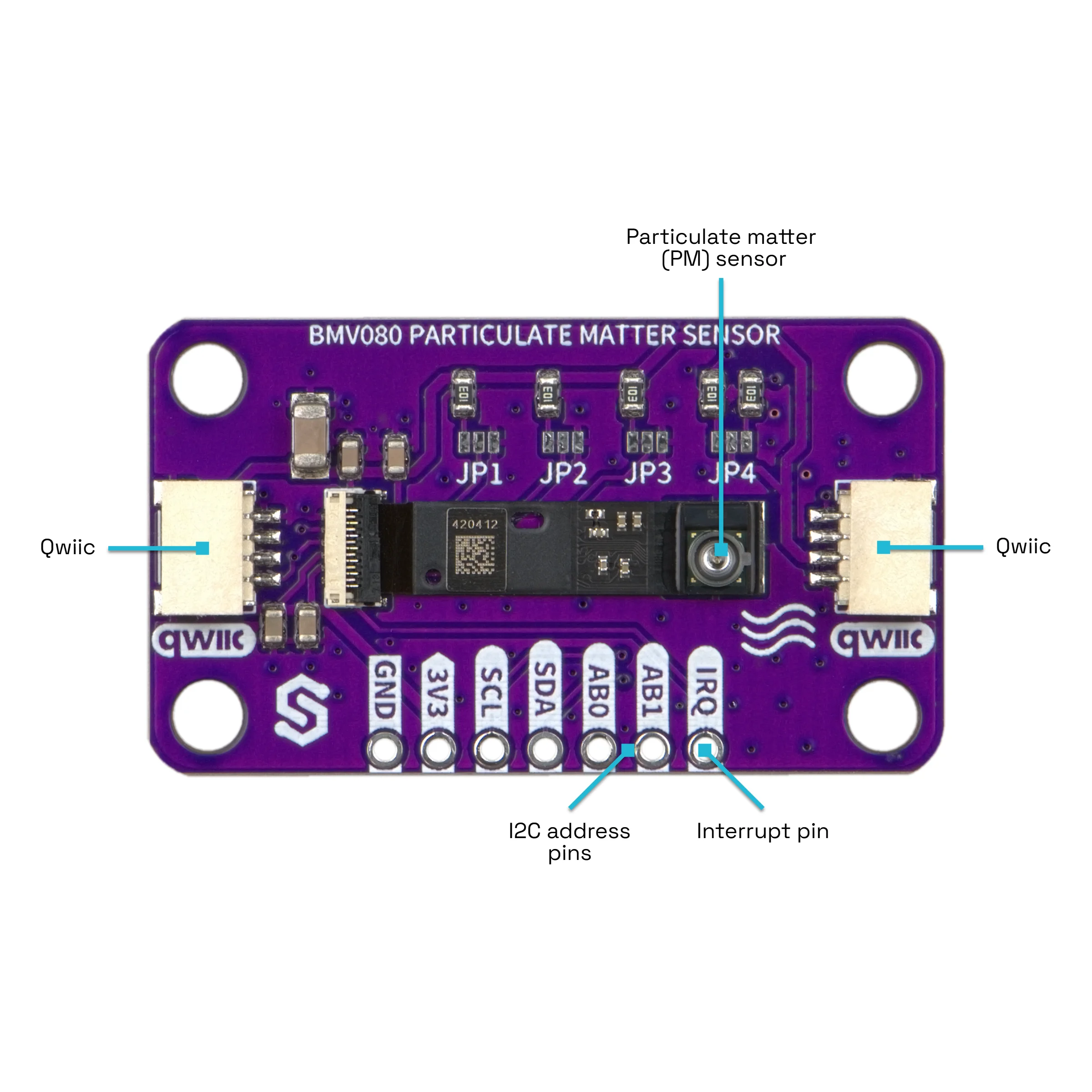
Key specifications
| Specification | Value |
|---|---|
| Interface | |
| Interface | I2C (default) or SPI, selected by jumper JP1 |
| Qwiic compatible | Yes, 2 connectors |
| Default I2C address | 0x57 |
| Address changeable | Yes, 0x54 to 0x57 with jumpers JP2 and JP3 |
| Breadboard compatible | Yes, 7-pin 2.54 mm header |
| Output rate | Up to 0.97 Hz, about one reading per second |
| Power | |
| Supply voltage | 3.3 V, no on-board regulator; the sensor's laser supply, on the same rail, is specified at 3.3 V ±5 %; absolute maximum 3.6 V |
| Logic level | 3.3 V |
| Current | Below 68 mA average while measuring, below 30 µA in sleep |
| Power, continuous mode | 181.9 mW typical |
| Power, duty cycling | 30.4 mW (1 reading per minute), 6.2 mW (per 5 min), 3.1 mW (per 10 min), 0.6 mW (per 60 min) |
| Other | |
| Sensor IC | BMV080 (Bosch Sensortec) |
| Measures | PM1, PM2.5 and PM10 mass concentration, in µg/m³ |
| Measurement range | 0 to 1000 µg/m³ (PM2.5), 1 µg/m³ resolution |
| Precision (PM2.5) | ±10 µg/m³ from 0 to 100 µg/m³, ±10 % from 101 to 1000 µg/m³, in continuous mode under the datasheet's test conditions |
| Smallest detectable particle | 0.5 µm |
| Measurement modes | Continuous, duty cycling |
| Measurement algorithms | High precision (default), balanced, fast response; duty cycling uses fast response |
| Start-up time | 1.9 s when polled, 2.9 s with the interrupt as trigger |
| Sensor operating temperature | +15 to +65 °C. The sensor warms itself by about 15 K while measuring continuously, so it can work below 15 °C ambient, depending on the thermal design around it |
| Operating humidity | 0 to 95 % RH, no condensation |
| Laser class | Class 1 (IEC 60825-1) |
| Dimensions | 38 x 22 mm |
| Mounting holes | 4 x 3.2 mm, for M3 screws |
Pinout
| Pin marking | Pin name | Description |
|---|---|---|
| GND | Ground | Common ground for power and signals. |
| 3V3 | 3.3 V supply | Powers the sensor directly. Supply 3.3 V only: there is no regulator on the board. |
| SCL | I2C clock / SPI SCK | I2C clock in I2C mode, serial clock in SPI mode. |
| SDA | I2C data / SPI MOSI | I2C data in I2C mode, data into the sensor in SPI mode. |
| AB0 | Address bit 0 / SPI MISO | Sets I2C address bit 0 through JP2. In SPI mode, data out of the sensor. |
| AB1 | Address bit 1 / SPI CSB | Sets I2C address bit 1 through JP3. In SPI mode, chip select (active low). |
| IRQ | Interrupt | The sensor's interrupt output, active low, with the sensor's own pull-up enabled by default. |
| Qwiic (x2) | Qwiic connectors | 3.3 V, GND, SDA and SCL, connected to the same lines as the header. |
Voltage and logic levels
| Connection | Supported voltage | Notes |
|---|---|---|
Header 3V3, Qwiic | 3.3 V | Feeds all four of the sensor's supply pins directly. The laser supply is the narrowest of them, specified at 3.3 V ±5 %; the other three accept a wider range, up to 3.3 V +5 %. The sensor's absolute maximum is 3.6 V. |
| Header signals, Qwiic SDA and SCL | 3.3 V logic | No level shifter on the board. |
This board runs on 3.3 V only. It has no voltage regulator, so never connect the header to 5 V, and use a controller with 3.3 V logic on its I2C or SPI pins.
The BMV080 is a Class 1 laser product: its design limits the emitted optical power to 0.5 mW. Its sensing region sits about 5 mm above the lens, and it works best at least 17 mm away from sharp edges, which make the airflow turbulent.
Dimensions
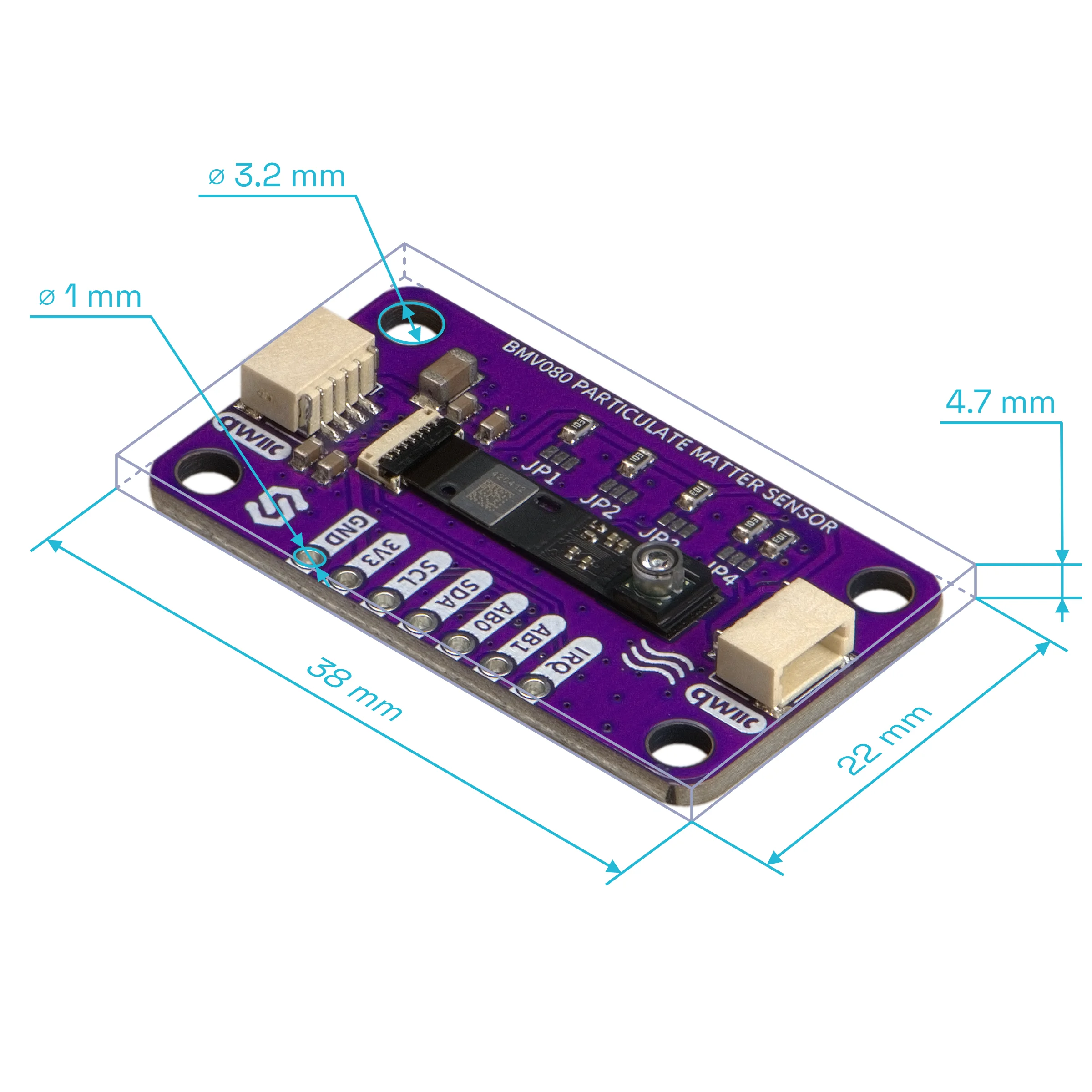
The board measures 38 x 22 mm. It has four mounting holes for M3 screws, each 3.2 mm in diameter.
Jumpers
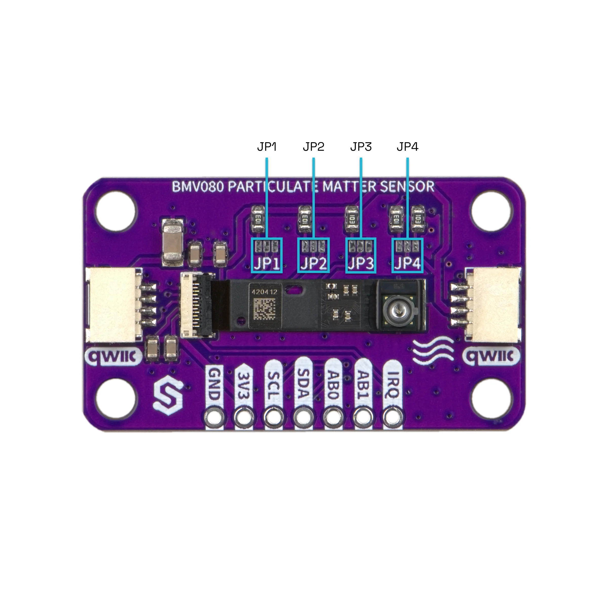
| Jumper | Default | Function |
|---|---|---|
| JP1 | Middle pad bridged to the 3.3 V (10 kΩ) side | Interface select. By default the sensor's protocol select pin is pulled high, which selects I2C. Cut the bridge and connect the middle pad to the GND pad to select SPI. |
| JP2, JP3 | Middle pad bridged to the 3.3 V (10 kΩ) side on both, address 0x57 | I2C address. JP2 sets bit 0 (AB0) and JP3 sets bit 1 (AB1). Cut a bridge and connect the middle pad to the GND pad to make that bit low: JP3 and JP2 both to GND gives 0x54, JP3 to GND only gives 0x55, JP2 to GND only gives 0x56. |
| JP4 | Closed | I2C pull-ups: 10 kΩ from SDA and from SCL to 3.3 V. Cut both bridges to remove them. In SPI mode the same pins carry MOSI and SCK, so a closed JP4 keeps the pull-ups on those two lines. The sensor picks SPI mode 0 or 3 from the level of SCK after CSB goes low. |
After cutting the bridge on JP2 or JP3, always connect that jumper's middle
pad to its GND pad. The sensor's address pins must not be left floating: a
floating AB0 or AB1 leaves the I2C address undefined. Keep JP1's middle
pad connected too: left unconnected it still selects I2C, but the sensor's
maker does not recommend it.
In SPI mode (JP1 to GND), leave JP2 and JP3 on their default 3.3 V side.
There AB0 is the sensor's MISO output and AB1 its CSB chip select, so
a GND bridge on JP2 ties MISO to GND, and one on JP3 holds CSB low.
No address is reserved or taken: 0x54 to 0x57 are ordinary I2C addresses,
and nothing else on the board uses the bus.
The sensor reads the interface select and address pins only when it powers
up. Change a jumper with the power off, or power the board off and on again
afterwards. Every library example sets the address with
#define BMV080_ADDR 0x57, so change that line to match a new address.
Hardware repository
There is no public hardware repository for this board yet.