Quick Start
Connect the breakout over Qwiic, install the library, and print the chlorine concentration in ppm.
You program the controller connected to this breakout. The breakout itself is not flashed: its ATtiny404 comes with factory firmware.
The board runs from 3.3 V only. It has no regulator, so the header 3V3 pins
and both Qwiic connectors share one 3.3 V supply that feeds every chip
directly. Do not connect 5 V to it.
- Arduino
- MicroPython
1. Connect the breakout board
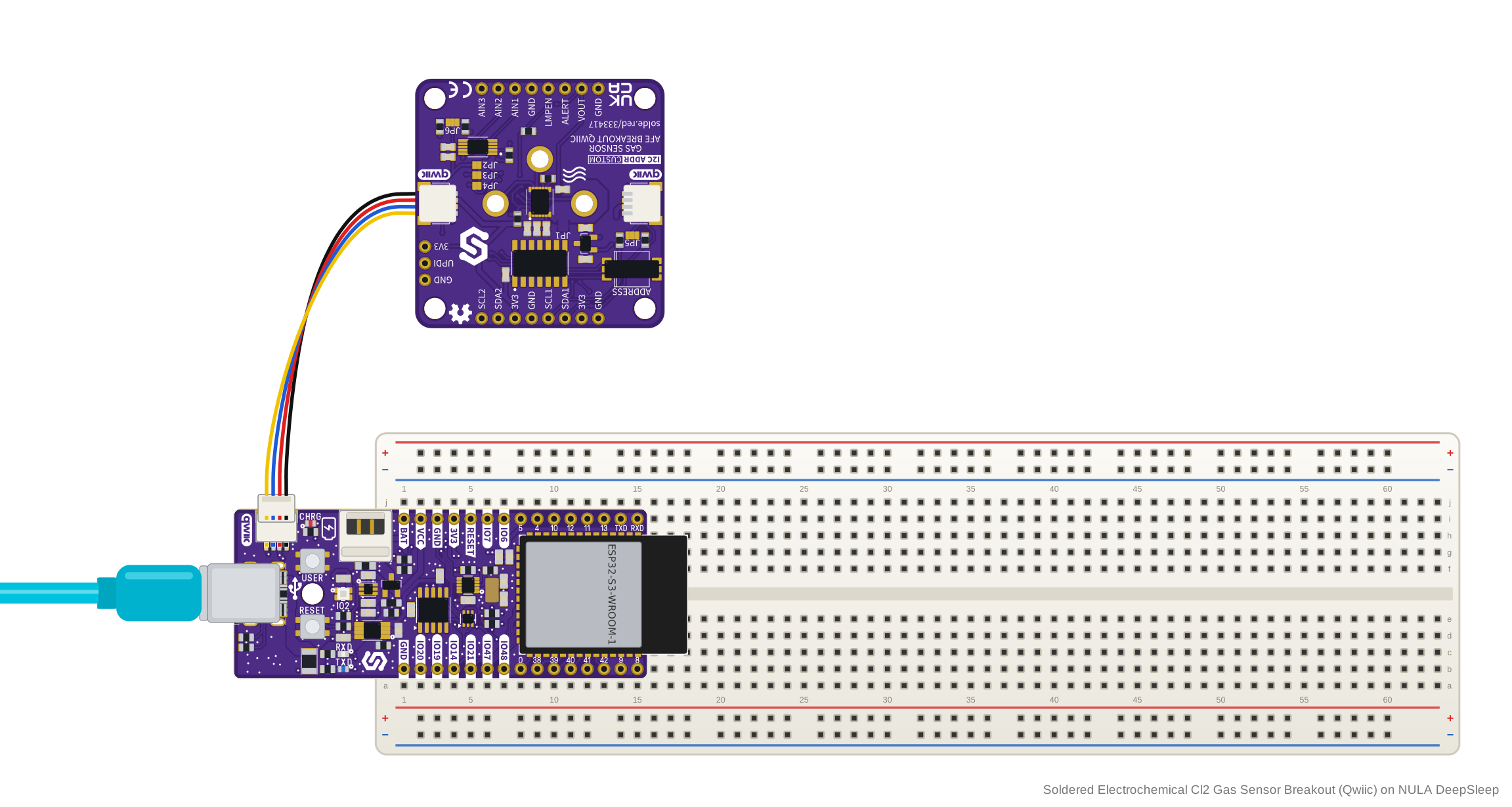
Plug a Qwiic cable into either Qwiic connector on the board and into the Qwiic
connector on your controller. Each Qwiic connector carries 3V3, GND and the
board's main I2C bus, so the one cable powers the board and connects it.
| NULA DeepSleep | Soldered Electrochemical Cl2 Gas Sensor Breakout (Qwiic) |
|---|---|
| Qwiic connector | Qwiic connector |
Without Qwiic: breadboard wiring
The board is not breadboard compatible, so it does not plug into a breadboard.
Solder the included header pins and wire the four pins of the top header's left
half to your controller with jumper wires. SDA1 and SCL1 are the same bus
as the Qwiic connectors.
| NULA DeepSleep | Soldered Electrochemical Cl2 Gas Sensor Breakout (Qwiic) |
|---|---|
| GND | GND |
| 3V3 | 3V3 |
| IO8 | SDA1 |
| IO9 | SCL1 |
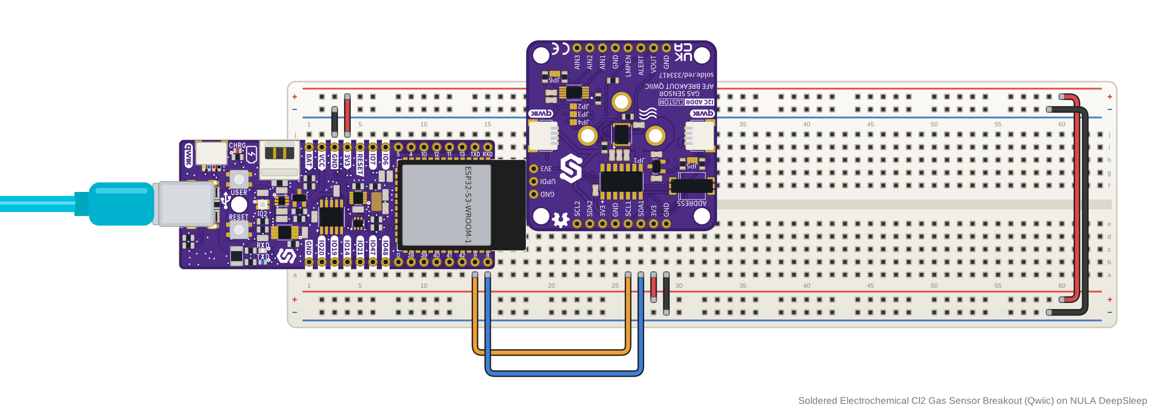
SDA2 and SCL2 on the same header are the board's internal bus between the
ATtiny404, the LMP91000 and the ADS1115. Connect your controller to SDA1 and
SCL1 (or Qwiic), never to SDA2 and SCL2.
2. Install the library
Install Electrochemical Gas Sensor Soldered from its GitHub repository.
🔗Electrochemical Gas Sensor Arduino library
Verified Arduino library at commit c4df54b
Tip: downloading from GitHub. On the library's GitHub page, click the green Code button and choose Download ZIP, then add it in Arduino IDE with Sketch → Include Library → Add .ZIP Library....
3. Run the first example
Open bridgeBoard from the library's examples. It creates the sensor at
address 0x30, the board's default, prints Sensor initialized successfully!
once the board answers, then prints a reading every 2.5 s.
The example creates the sensor with SENSOR_CO, the library's preset for the
carbon monoxide cell. The library turns the cell current into ppm with the
preset's sensitivity and gain settings, so before you upload, change that line
to this board's chlorine preset:
ElectrochemicalGasSensor sensor(SENSOR_CL2, 0x30);
The header comment says to set the address with the jumpers on the back of the board. On this board the ADDRESS switch on the top side sets the address, and it is 0x30 by default, the address the example uses (see Hardware Details).
The header comment also says LMPEN is hardwired to GND. On this board a 10 kΩ
resistor holds LMPEN low and it is wired to the ATtiny404, so you leave it
unconnected (see Hardware Details).
/**
 **************************************************
 *
 * @file        bridgeBoard.ino
 * @brief       See how to init a sensor on the new ATtiny404 bridge board revision,
 *
 *              To successfully run the sketch:
 *              - Set the desired address using the jumpers on the back of the board
 *                (address = 0x30 + jumper offset, giving a range of 0x30-0x37)
 *              - Run the sketch and open serial monitor at 115200 baud!
 *
 *              Note: on this board revision, LMPEN is hardwired to GND, so there's
 *              no configPin argument to pass - the constructor's third argument
 *              is ignored whenever the address falls in the bridge range (0x30-0x37).
 *
 *
 * @authors     @ soldered.com
 ***************************************************/

// Include the required library
#include "Electrochemical-Gas-Sensor-SOLDERED.h"

// Any additional boards on the same bus just need a different jumper setting
// (0x30-0x37), same as twoSensors.ino does for legacy boards with 0x49/0x4A/0x4B.
ElectrochemicalGasSensor sensor(SENSOR_CO, 0x30);

void setup()
{
    Serial.begin(115200); // For debugging

    // Init the breakout
    if (!sensor.begin())
    {
        // Can't init? Notify the user and go to infinite loop
        Serial.println("ERROR: Can't init the sensor! Check connections and jumper address!");
        while (true)
            delay(100);
    }

    Serial.println("Sensor initialized successfully!");
}

void loop()
{
    // Make the reading
    double reading = sensor.getPPM();

    // If PPB is more relevant for your sensor, you can use:
    // double reading = sensor.getPPB();

    // Print the reading with 5 digits of precision
    Serial.print("Sensor reading: ");
    Serial.print(reading, 5);
    Serial.println(" PPM");

    // Wait a bit before reading again
    delay(2500);
}
4. Check the result
Open the Serial Monitor at 115200 baud. When the board answers, it prints
Sensor initialized successfully!, then a line every 2.5 s: Sensor reading: ,
the chlorine concentration in ppm with five decimals, and PPM. The library
reports any result below zero as 0. A run on this board in clean air printed:
Sensor initialized successfully!
Sensor reading: 0.00124 PPM
Sensor reading: 0.00122 PPM
Sensor reading: 0.00132 PPM
Sensor reading: 0.00137 PPM
If you see ERROR: Can't init the sensor! Check connections and jumper address!
instead, the board did not answer at 0x30.
5. If it does not work
Continue with Troubleshooting and retry this smallest example after each change.
1. Connect the breakout board
Plug a Qwiic cable into either Qwiic connector on the board and into the Qwiic
connector on your controller. Each Qwiic connector carries 3V3, GND and the
board's main I2C bus, so the one cable powers the board and connects it.
| NULA DeepSleep | Soldered Electrochemical Cl2 Gas Sensor Breakout (Qwiic) |
|---|---|
| Qwiic connector | Qwiic connector |
The module's example opens I2C bus 0 with SCL on pin 22 and SDA on pin 21.
Change those pin numbers in the example if your controller's Qwiic connector or
the pins you wire are elsewhere.
Without Qwiic: breadboard wiring
The board is not breadboard compatible, so it does not plug into a breadboard.
Solder the included header pins and wire the four pins of the top header's left
half to your controller with jumper wires: SDA1 to the pin you use as sda,
SCL1 to the pin you use as scl.
| NULA DeepSleep | Soldered Electrochemical Cl2 Gas Sensor Breakout (Qwiic) |
|---|---|
| GND | GND |
| 3V3 | 3V3 |
| IO8 | SDA1 |
| IO9 | SCL1 |
SDA2 and SCL2 on the same header are the board's internal bus between the
ATtiny404, the LMP91000 and the ADS1115. Connect your controller to SDA1 and
SCL1 (or Qwiic), never to SDA2 and SCL2.
2. Install the module
After installing the mpremote package, install the library on your board using the following command:
mpremote mip install github:SolderedElectronics/Soldered-ElectrochemicalGasSensor-MicroPython-Library
Or, if you're running a Windows OS:
python -m mpremote mip install github:SolderedElectronics/Soldered-ElectrochemicalGasSensor-MicroPython-Library
The library is also listed on mim.
These pages describe the module at commit 623e1e6. The command above names no commit, so it installs the repository as it is on the day you run it.
🔗Electrochemical Gas Sensor MicroPython library
Module source at commit 623e1e6, the version these pages describe
Tip: downloading from GitHub. Without mpremote, open the module's .py
file on GitHub and click Download raw file, then open it in Thonny and use
File → Save as... → MicroPython device to copy it onto the board. This
library needs all three files: ElectrochemicalGasSensor.py, ads1115.py and
lmp91000.py.
3. Run the first example
This is the module's electrochemical-bridgeBoard.py example. It creates the
sensor at address 0x30, the board's default, and prints a reading every 2.5 s.
The example uses SENSOR_O3, the module's preset for the ozone cell. The module
turns the cell current into ppm with the preset's sensitivity and gain settings,
so before you run it, change SENSOR_O3 to SENSOR_CL2 in both places: the
import line and the line that creates the sensor.
from ElectrochemicalGasSensor import ElectrochemicalGasSensor, SENSOR_CL2
sensor = ElectrochemicalGasSensor(SENSOR_CL2, i2c, adc_addr=0x30)
The example's comment says to set the address with the jumpers on the back of the board. On this board the ADDRESS switch on the top side sets the address, and it is 0x30 by default, the address the example uses (see Hardware Details).
The same comment says LMPEN is hardwired to GND. On this board a 10 kΩ
resistor holds LMPEN low and it is wired to the ATtiny404, so you leave it
unconnected (see Hardware Details).
# FILE: electrochemical-bridgeBoard.py
# AUTHOR: Fran Fodor @ Soldered
# BRIEF: Single sensor PPM reading example for the ATtiny404 bridge board revision,
#        which allows daisy-chaining multiple boards on one I2C bus.
# LAST UPDATED: 2026-07-23

# Connecting diagram:
#
# Qwiic------------------------>Qwiic
#
# Note: on this board revision, LMPEN is hardwired to GND, so there's no
# config_pin to set - it's ignored whenever adc_addr falls in the bridge
# range (0x30-0x37). Set the desired address using the jumpers on the back
# of the board before powering it on.

from machine import I2C, Pin
import time
from ElectrochemicalGasSensor import ElectrochemicalGasSensor, SENSOR_O3

# Initialize I2C
i2c = I2C(0, scl=Pin(22), sda=Pin(21))

# (address = 0x30 + jumper offset, giving a range of 0x30-0x37).
# Any additional boards on the same bus just need a different jumper
# setting, same as twoSensors.py does for legacy boards with 0x49/0x4A/0x4B.
sensor = ElectrochemicalGasSensor(SENSOR_O3, i2c, adc_addr=0x30)

# -------------------------------------------------------------------------
# Setup
# -------------------------------------------------------------------------
print("Electrochemical Gas Sensor - ATtiny Bridge Board Example")

if not sensor.begin():
    print("ERROR: Can't init the sensor! Check connections and jumper address!")
    while True:
        time.sleep_ms(100)

print("Sensor initialized successfully!")

# -------------------------------------------------------------------------
# Main loop
# -------------------------------------------------------------------------
while True:
    reading = sensor.getPPM()

    # If PPB is more relevant for your sensor, use:
    # reading = sensor.getPPB()

    print("Sensor reading: {:.5f} PPM".format(reading))

    time.sleep_ms(2500)
🔗Open the complete example
Examples/electrochemical-bridgeBoard.py at commit 623e1e6
4. Check the result
When the board answers, the shell shows the example's title line and
Sensor initialized successfully!, then a line every 2.5 s: Sensor reading: ,
the chlorine concentration in ppm with five decimals, and PPM. The module
reports any result below zero as 0. A run on this board in clean air printed:
Electrochemical Gas Sensor - ATtiny Bridge Board Example
Sensor initialized successfully!
Sensor reading: 0.00125 PPM
Sensor reading: 0.00124 PPM
Sensor reading: 0.00125 PPM
Sensor reading: 0.00133 PPM
If you see ERROR: Can't init the sensor! Check connections and jumper address!
instead, the board did not answer at 0x30.
5. If it does not work
Continue with Troubleshooting and retry this smallest example after each change.