Hardware Details
The board has two I2C buses. The Qwiic connectors and the SDA1/SCL1 pins
reach only the ATtiny404, which answers at 0x30 to 0x37. The ATtiny404 runs
the LMP91000 front end and the ADS1115 ADC on a second bus, SDA2/SCL2, where
the LMP91000 sits at 0x48 and the ADS1115 at 0x49. A 2.5 V voltage reference
sets the front end's reference voltage. The front end's analog output VOUT,
the ADC's ALERT pin and its free inputs AIN1 to AIN3 are on the header for
your own use.
Key specifications
| Specification | Value |
|---|---|
| MCU | |
| Bridge MCU | Microchip ATtiny404 (factory firmware) |
| Interface | |
| Interface | I2C, analog, digital GPIO |
| Qwiic compatible | Yes, 2 connectors |
| Default I2C address | 0x30 |
| I2C address changeable | Yes, 0x30 to 0x37 with the ADDRESS switch |
| Breadboard compatible | No |
| Header pins | VOUT (analog out), ALERT, AIN1 to AIN3 (analog in) |
| Power | |
| Supply voltage | 3.3 V, no regulator; the Qwiic connectors share this supply |
| Logic level | 3.3 V only |
| Other | |
| Gas | Hydrogen sulphide (H2S) |
| Gas cell | SGX-4H2S-300, electrochemical |
| Measurement range | 0 to 300 ppm H2S; max overload 500 ppm |
| Measurement accuracy | Repeatability < ±2% H2S equivalent; linearity < 2% (0 to 300 ppm); resolution < 0.1 ppm typical |
| Response time | T90 under 30 s |
| Operating conditions | -30 to 50 °C, 15 to 90% RH |
| Expected cell life | Over 24 months in air |
| Analog front end | Texas Instruments LMP91000 |
| ADC | Texas Instruments ADS1115, 16-bit |
| Dimensions | 38 x 38 mm |
Pinout
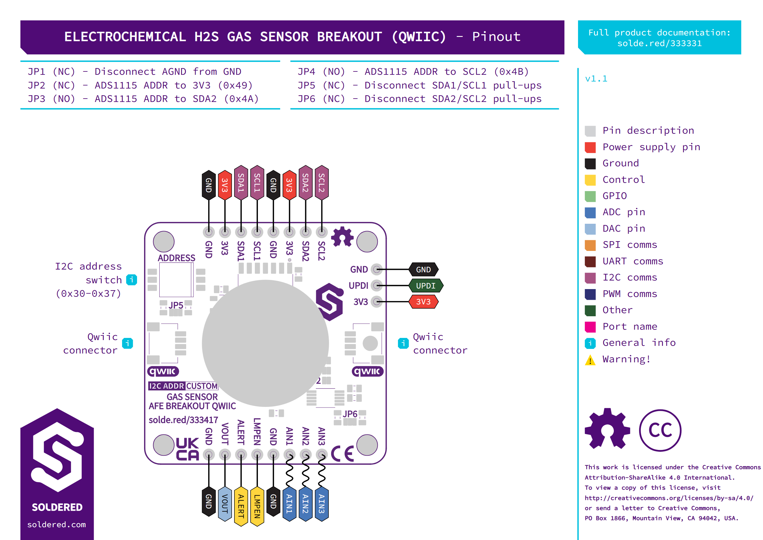
| Pin marking | Pin name | Description |
|---|---|---|
| 3V3 | Power | 3.3 V supply in. On the top row and the side row, shared with both Qwiic connectors. |
| GND | Ground | Ground. On all three rows. |
| SDA1, SCL1 | Qwiic I2C bus | The same bus as the Qwiic connectors, to the ATtiny404. 10 kΩ pull-ups to 3V3 (JP5). |
| SDA2, SCL2 | On-board I2C bus | The bus between the ATtiny404, the LMP91000 and the ADS1115. 10 kΩ pull-ups to 3V3 (JP6). |
| VOUT | Analog output | The LMP91000 output voltage, which the ADS1115 also reads on its input AIN0. |
| ALERT | ADC alert | The ADS1115 ALERT/RDY output, with a 10 kΩ pull-up to 3V3. Also wired to the ATtiny404. |
| LMPEN | Front-end enable | The LMP91000 MENB pin, held low by a 10 kΩ resistor to GND. Also wired to the ATtiny404. |
| AIN1, AIN2, AIN3 | Analog inputs | The ADS1115's other three inputs, free for your own analog signals. |
| UPDI | Programming | The ATtiny404 programming pin. |
Voltage and logic levels
| Connection | Supported voltage | Notes |
|---|---|---|
| 3V3 pins and Qwiic connectors | 3.3 V | There is no regulator: everything on the board runs from this supply. |
| SDA1, SCL1, SDA2, SCL2 | 3.3 V logic | Pulled up to 3V3 through 10 kΩ. |
Power the board from 3.3 V only. It has no regulator, so the header and both Qwiic connectors feed the 3.3 V supply straight to the chips.
Dimensions
The board measures 38 x 38 mm and has four 3.2 mm mounting holes. The gas cell sits on the underside.
Jumpers
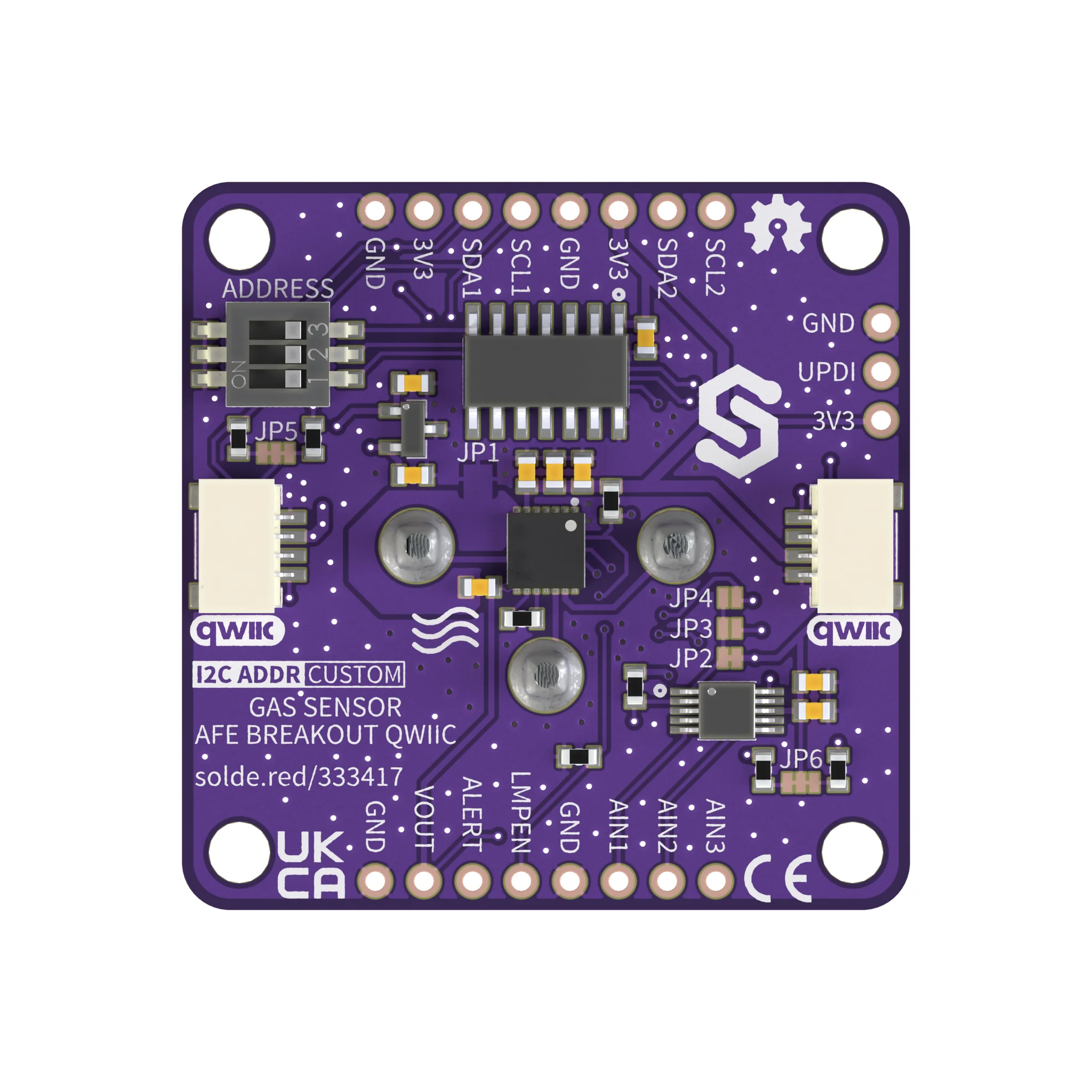
| Jumper | Default | Function |
|---|---|---|
| ADDRESS switch (1 to 3) | Address 0x30 | Sets the board's I2C address on the Qwiic bus, from 0x30 to 0x37. |
| JP1 | Closed | Joins the front end's analog ground (AGND) to GND. Cut it to separate them. |
| JP2 to JP4 | JP2 closed, JP3 and JP4 open | Set the ADS1115 address on the on-board bus: JP2 ties ADDR to 3V3 (0x49), JP3 ties it to SDA2 (0x4A), JP4 ties it to SCL2 (0x4B). |
| JP5 | Closed | Connects the 10 kΩ pull-ups on SDA1 and SCL1 (the Qwiic bus). Cut it to disconnect them. |
| JP6 | Closed | Connects the 10 kΩ pull-ups on SDA2 and SCL2 (the on-board bus). Cut it to disconnect them. |
Close only one of JP2, JP3 and JP4. With JP2 closed, closing JP3 or JP4 ties SDA2 or SCL2 to 3V3, and closing JP3 and JP4 together ties SDA2 to SCL2. Either way the on-board bus stops working and the board cannot take readings.
When you use the board at 0x30 to 0x37, leave JP2 to JP4 as shipped: JP2
closed, JP3 and JP4 open. In that mode the Arduino library and the MicroPython
module send the ATtiny404 only the ADC gain and data rate, never an ADS1115
address. To put several boards on the Qwiic bus at 0x30 to 0x37, use the
ADDRESS switch.