Jumpers
Inkplate 7SPECTRA has eight solder jumpers, JP1 to JP8, on the component side. NC (normally closed) jumpers are bridged at the factory and you cut them to change the connection; the NO (normally open) jumper is open until you bridge it with solder. The pinout below lists them at the top.
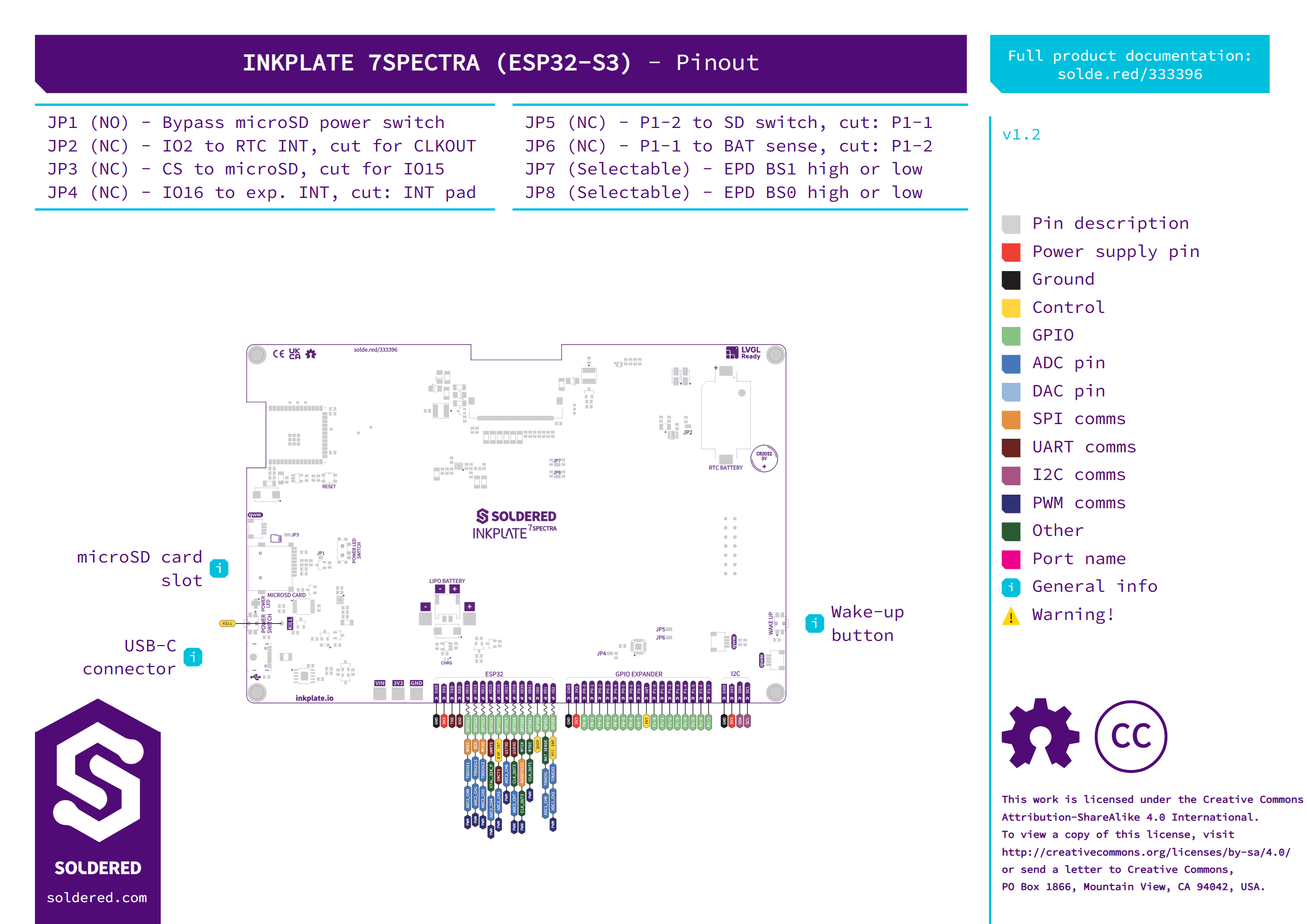
| Jumper | Default state | Function |
|---|---|---|
| JP1 | Open (NO) | Bypasses the microSD card's power switch. |
| JP2 | Closed (NC) | Connects IO2 to the RTC interrupt (INT). Cut it for CLKOUT. |
| JP3 | Closed (NC) | Connects CS to the microSD card. Cut it for IO15. |
| JP4 | Closed (NC) | Connects IO16 to the GPIO expander's interrupt (INT). Cut it to use the INT pad. |
| JP5 | Closed (NC) | Connects expander pin P1-2 to the microSD power switch. Cut it for P1-1. |
| JP6 | Closed (NC) | Connects expander pin P1-1 to the battery voltage measurement. Cut it for P1-2. |
| JP7 and JP8 | Selectable | Set the panel's interface-select lines high or low: JP7 for BS1, JP8 for BS0. |
Keep JP7 and JP8 set low. Both libraries drive BS0 and BS1 low to select the panel's 4-wire SPI interface, so either line set high selects an interface mode neither library drives.
Leave JP5 and JP6 closed. Both libraries switch the microSD supply with P1-2 and the battery measurement with P1-1; after cutting either jumper, the library no longer switches the part it expects.