Hardware Details
The front of the GRID holds 16 key pads in a 4x4 grid, with a WS2812B-2020 RGB LED in the middle of each one. Sixteen silicone keys sit over the pads in a plastic key holder. On the back, an ATtiny404 microcontroller scans the keys, drives all 16 LEDs on one data line and answers your controller on I2C. The board has no voltage regulator: everything runs from the 3.3 V that arrives on a Qwiic connector.
Key specifications
| Specification | Value |
|---|---|
| Interface | |
| Interface | I2C |
| Qwiic compatible | Yes, 4 Qwiic connectors |
| Default I2C address | 0x30 |
| I2C address changeable | Yes, by command, 0x08 to 0x77, stored in EEPROM |
| I2C pull-ups | 2 × 10 kΩ to 3.3 V, disconnected by cutting JP5 |
| Breadboard compatible | No |
| Power | |
| Supply voltage | 3.3 V over Qwiic, no onboard regulator |
| Logic level | 3.3 V only |
| Other | |
| Controller | Microchip ATtiny404, preprogrammed |
| Buttons | 16 silicone keys in a 4x4 matrix, plastic key holder included |
| LEDs | 16 × WS2812B-2020 RGB, one under each key, 0 to 255 per colour |
| Connectors | 4 × Qwiic, 4 sets of I2C solder pads, UPDI programming pads |
| Dimensions | 60 × 60 mm |
Pinout
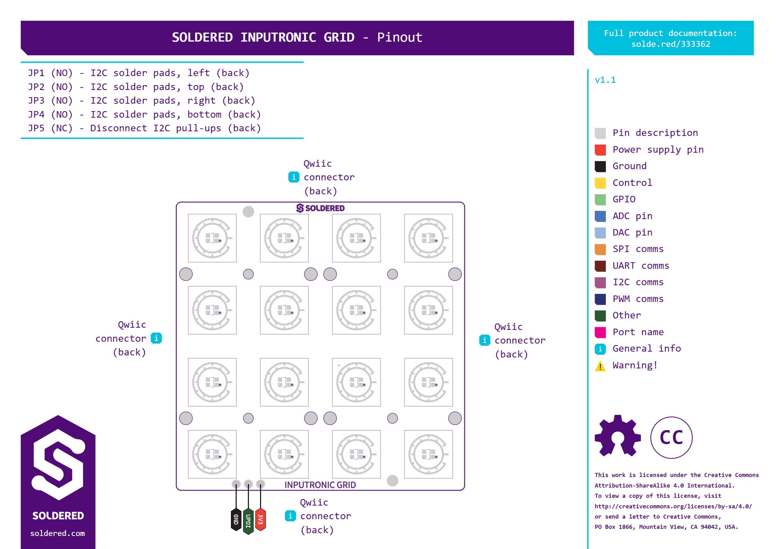
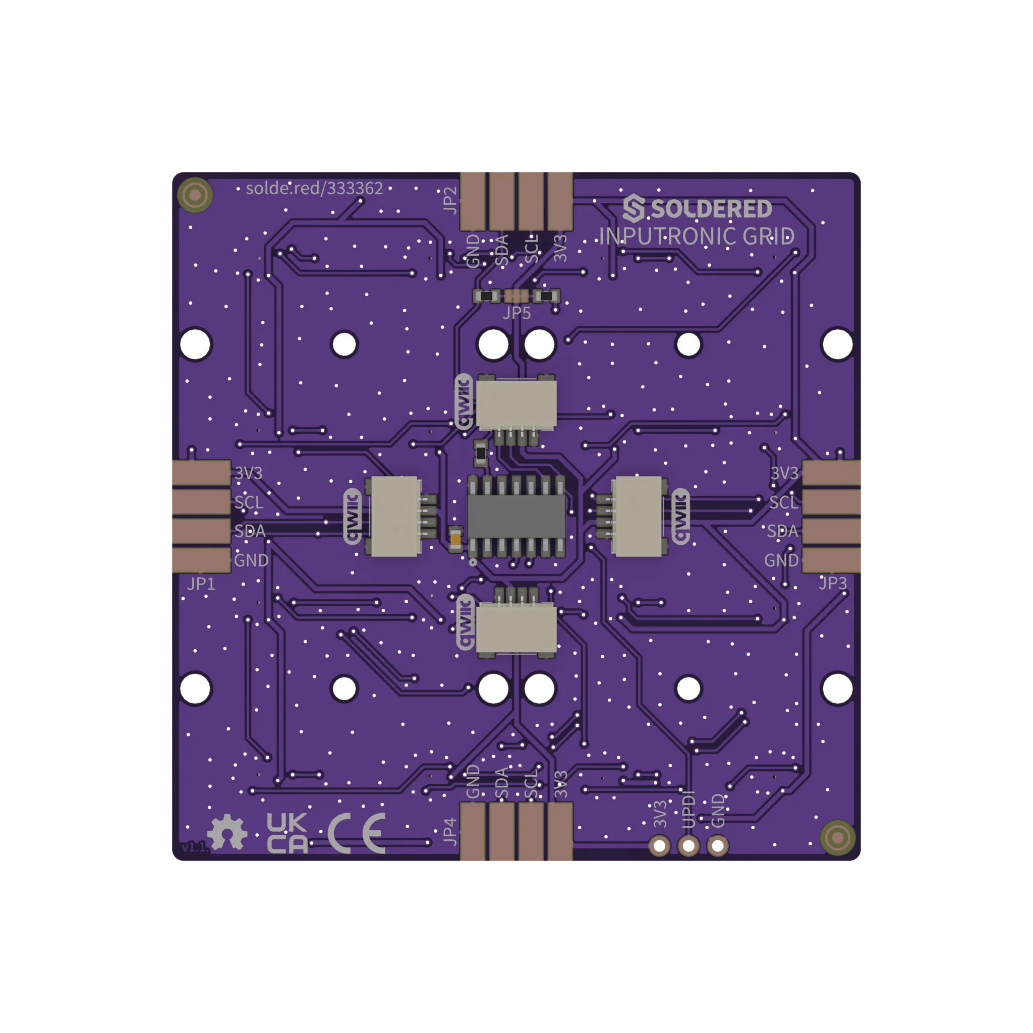
Seen from the back, as in the photo above, the JP1 pads are at the left
edge, JP2 at the top, JP3 at the right and JP4 at the bottom. The label
is printed next to each set of pads.
| Connector | Pins | Description |
|---|---|---|
| Qwiic (×4) | 3V3, GND, SDA, SCL | Power and I2C. All four are wired in parallel: use any one, and the others pass the bus on to more Qwiic boards. |
I2C solder pads JP1 to JP4 | 3V3, SCL, SDA, GND | The same four lines at each edge of the back, for soldering wires instead of using a Qwiic cable. |
| UPDI pads | 3V3, UPDI, GND | Programming interface of the ATtiny404, which comes preprogrammed. You do not need it to use the board. |
Voltage and logic levels
| Connection | Supported voltage | Notes |
|---|---|---|
3V3 (Qwiic or solder pads) | 3.3 V | The board's only supply. It powers the ATtiny404 and all 16 LEDs; there is no regulator on the board. |
SDA, SCL | 3.3 V logic | Each line has a 10 kΩ pull-up to 3.3 V while JP5 is closed. |
The GRID is a 3.3 V-only board with no regulator and no level shifter. Connect it to a 3.3 V supply and a 3.3 V I2C bus.
The WS2812B-2020 datasheet linked for this board rates the LED supply at 3.7 to 5.3 V. On the GRID the LEDs run from the 3.3 V supply, below that range.
Dimensions
The board measures 60 × 60 mm.
Jumpers
| Jumper | Default | Function |
|---|---|---|
JP5 | Closed | Connects the 10 kΩ pull-ups on SDA and SCL to 3.3 V. Cut it to disconnect both when another board on the bus already has pull-ups. |
JP1 to JP4 | Open | I2C solder pads (3V3, SCL, SDA, GND), one set at each edge, on the same lines as the Qwiic connectors. Nothing is set by them. |
The I2C address is not set with a jumper: you change it with a command, see Change the I2C address.