Quick Start
Connect the GRID with a Qwiic cable, install the library and run its button and LED example. Every press of a pad switches that pad's LED on or off, and the press is printed, so you see straight away that the buttons, the LEDs and the I2C link all work.
You program the controller connected to this breakout. The breakout itself is not flashed.
- Arduino
- MicroPython
1. Connect the breakout board
Plug a Qwiic cable into any of the four Qwiic connectors on the back of the GRID and into the Qwiic connector on your controller. No soldering needed. The cable also brings the board its 3.3 V supply, and the other three connectors pass the bus on to more Qwiic boards.
| NULA DeepSleep | Soldered Inputronic GRID |
|---|---|
| Qwiic connector | Qwiic connector |
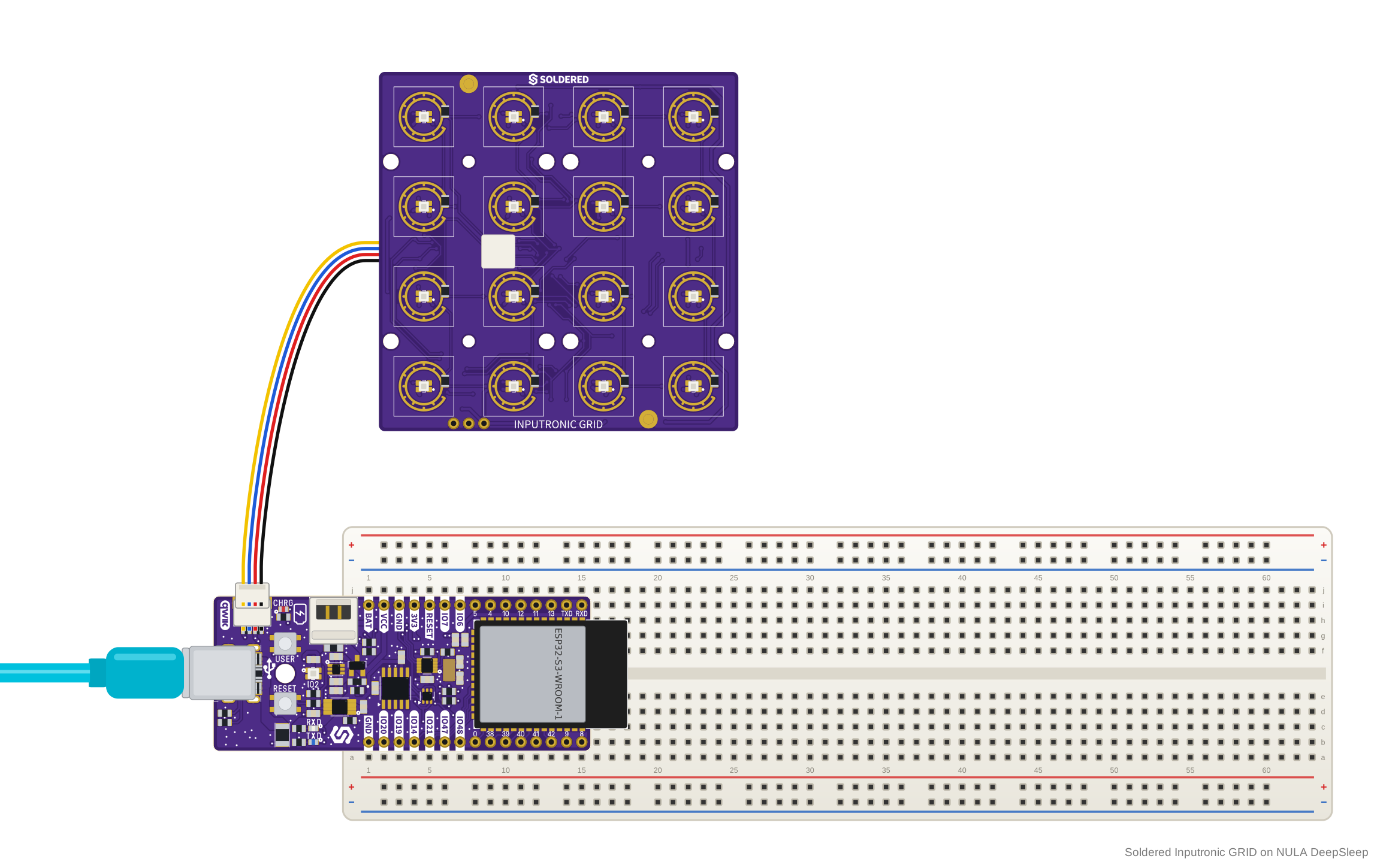
Without Qwiic: breadboard wiring
The GRID does not plug into a breadboard. Instead, solder four wires to one of
the I2C solder pad sets (JP1 to JP4) at the edges of the back. Each set is
marked 3V3, SCL, SDA and GND, and carries the same lines as the Qwiic
connectors.
| Controller | Soldered Inputronic GRID |
|---|---|
| 3V3 | 3V3 |
| GND | GND |
| SDA | SDA |
| SCL | SCL |
The board runs on 3.3 V only. Connect it to a 3.3 V supply and 3.3 V I2C lines.
2. Install the library
Install Soldered Inputronic GRID by downloading it from its GitHub repository and adding the ZIP in Arduino IDE (see the tip below).
🔗Soldered Inputronic GRID Arduino library
Verified Arduino library at commit 399b832
Tip: downloading from GitHub. On the library's GitHub page, click the green Code button and choose Download ZIP, then add it in Arduino IDE with Sketch → Include Library → Add .ZIP Library....
3. Run the first example
This is ButtonLEDControl.ino, the library's own example. Each press of a pad
toggles its LED: on in the colour of its row (red, green, blue and orange for
rows 0 to 3), off on the next press.
/**
 **************************************************
 *
 * @file        ButtonLEDControl.ino
 * @brief       Example showing button-driven LED toggle on the Inputronic Grid.
 *
 *              Each button toggles its corresponding LED on or off.
 *              First press turns the LED on in a row-specific color;
 *              second press turns it off.
 *
 *              Demonstrates reading individual pads by row/col coordinate
 *              and reacting with per-LED color control using the same
 *              row/col coordinates.
 *
 *              Hardware wiring:
 *              - Connect Inputronic Grid to host via Qwiic / I2C
 *                (SDA, SCL, 3V3, GND).
 *
 * @authors     Josip Šimun Kuči @ soldered.com
 ***************************************************/

#include <InputronicGrid.h>

InputronicGrid grid;

// Toggle state per button, indexed by [row][col]
bool ledOn[4][4] = {};

// Colors per row (R, G, B)
const uint8_t rowColor[4][3] = {
    {255,   0,   0},  // row 0 — red
    {  0, 255,   0},  // row 1 — green
    {  0,   0, 255},  // row 2 — blue
    {255, 128,   0},  // row 3 — orange
};

// Previous pad state per [row][col] for edge detection
bool prevState[4][4] = {};

void setup()
{
    Serial.begin(115200);

    if (!grid.begin())
    {
        Serial.println("Inputronic GRID not found. Check wiring.");
        while (1)
            ;
    }

    grid.clearLEDs();
    Serial.println("Press any button to toggle its LED.");
}

void loop()
{
    for (uint8_t row = 0; row < 4; row++)
    {
        for (uint8_t col = 0; col < 4; col++)
        {
            bool pressed = grid.readPad(row, col);

            if (pressed && !prevState[row][col])
            {
                ledOn[row][col] = !ledOn[row][col];

                if (ledOn[row][col])
                    grid.setLED(row, col, rowColor[row][0], rowColor[row][1], rowColor[row][2], 255);
                else
                    grid.setLED(row, col, 0, 0, 0, 255);

                Serial.print("Button (row ");
                Serial.print(row);
                Serial.print(", col ");
                Serial.print(col);
                Serial.print(") → LED ");
                Serial.println(ledOn[row][col] ? "ON" : "OFF");
            }

            prevState[row][col] = pressed;
        }
    }

    delay(20);
}
4. Check the result
Open the Serial Monitor at 115200 baud. All LEDs start off. Press the pad at row 0, column 0 twice: its LED lights red, then turns off, and the Serial Monitor shows:
Press any button to toggle its LED.
Button (row 0, col 0) → LED ON
Button (row 0, col 0) → LED OFF
If the board does not answer on I2C, the sketch prints
Inputronic GRID not found. Check wiring. and stops.
Light a pad when you press it explains every function the sketch uses.
5. If it does not work
Continue with Troubleshooting and retry this smallest example after each change.
1. Connect the breakout board
Plug a Qwiic cable into any of the four Qwiic connectors on the back of the GRID and into the Qwiic connector on your controller. No soldering needed. The cable also brings the board its 3.3 V supply.
| NULA DeepSleep | Soldered Inputronic GRID |
|---|---|
| Qwiic connector | Qwiic connector |
Created without an I2C object, the module uses I2C bus 0 with SCL on pin 22
and SDA on pin 21, on the ports it recognises: ESP32, ESP8266 and one
Soldered board. On a board it does not recognise, or with other pins, use the commented lines at the top of the example to pass
your own I2C object.
Without Qwiic: breadboard wiring
The GRID does not plug into a breadboard. Instead, solder four wires to one of
the I2C solder pad sets (JP1 to JP4) at the edges of the back. Each set is
marked 3V3, SCL, SDA and GND, and carries the same lines as the Qwiic
connectors.
| Controller | Soldered Inputronic GRID |
|---|---|
| 3V3 | 3V3 |
| GND | GND |
| SDA | SDA |
| SCL | SCL |
The board runs on 3.3 V only. Connect it to a 3.3 V supply and 3.3 V I2C lines.
2. Install the module
Install the Soldered Inputronic GRID MicroPython library. After installing the mpremote package, install it on your board with the command from the library's README:
mpremote mip install github:SolderedElectronics/Soldered-Inputronic-GRID-MicroPython-Library
Or, on Windows:
python -m mpremote mip install github:SolderedElectronics/Soldered-Inputronic-GRID-MicroPython-Library
🔗Soldered Inputronic GRID MicroPython library
Verified MicroPython module at commit 36d3def
Tip: downloading from GitHub. Without mpremote, open the module's .py
file on GitHub and click Download raw file, then open it in Thonny and use
File → Save as... → MicroPython device to copy it onto the board.
3. Run the first example
This is Examples/ButtonLEDControl.py, the library's own example. Each press of
a pad toggles its LED: on in the colour of its row (red, green, blue and orange
for rows 0 to 3), off on the next press. Save it to your board and run it.
# FILE: ButtonLEDControl.py
# AUTHOR: Josip Šimun Kuči @ Soldered
# BRIEF: Example showing button-driven LED toggle on the Inputronic GRID.
#        Each button toggles its corresponding LED on or off.
#        First press turns the LED on in a row-specific color;
#        second press turns it off.
#        Demonstrates reading individual pads by row/col coordinate
#        and reacting with per-LED color control using the same coordinates.
# WORKS WITH: Inputronic GRID: www.soldered.com
# LAST UPDATED: 2026-05-12

from machine import I2C, Pin
from InputronicGrid import InputronicGrid
import time

# If you aren't using the Qwiic connector, manually enter your I2C pins:
# i2c = I2C(0, scl=Pin(22), sda=Pin(21))
# grid = InputronicGrid(i2c=i2c)

grid = InputronicGrid()
grid.clearLEDs()
print("Press any button to toggle its LED.")

# Toggle state per button, indexed by [row][col]
ledOn = [[False] * 4 for _ in range(4)]

# Colors per row (R, G, B)
rowColor = [
    (255,   0,   0),  # row 0 — red
    (  0, 255,   0),  # row 1 — green
    (  0,   0, 255),  # row 2 — blue
    (255, 128,   0),  # row 3 — orange
]

# Previous pad state per [row][col] for edge detection
prevState = [[False] * 4 for _ in range(4)]

while True:
    for row in range(4):
        for col in range(4):
            pressed = grid.readPad(row, col)

            if pressed and not prevState[row][col]:
                ledOn[row][col] = not ledOn[row][col]

                if ledOn[row][col]:
                    r, g, b = rowColor[row]
                    grid.setLED(row, col, r, g, b, 255)
                else:
                    grid.setLED(row, col, 0, 0, 0, 255)

                print("Button (row {}, col {}) → LED {}".format(
                    row, col, "ON" if ledOn[row][col] else "OFF"))

            prevState[row][col] = pressed

    time.sleep_ms(20)
4. Check the result
All LEDs start off. Press the pad at row 0, column 0 twice: its LED lights red, then turns off, and the shell shows:
Press any button to toggle its LED.
Button (row 0, col 0) → LED ON
Button (row 0, col 0) → LED OFF
If the board does not answer on I2C, the module raises an exception with the
message Inputronic GRID not found. Check wiring.
Light a pad when you press it explains every function the example uses.
5. If it does not work
Continue with Troubleshooting and retry this smallest example after each change.