Hardware Details
Soldered NULA CAN ESP32-S3 pairs an ESP32-S3-WROOM-1-N8R8 module with an NXP TJA1441A CAN transceiver. The transceiver is wired to the ESP32-S3's TWAI controller (Espressif's name for its CAN controller), and its bus lines come out on a three-pin terminal block. Twenty GPIO (general-purpose input/output pins) sit on two 13-pin, 2.54 mm headers that fit a breadboard. This page covers what each pin does, how the board is powered and what its three solder jumpers are for.
Key specifications
| Specification | Value |
|---|---|
| MCU | |
| MCU | ESP32-S3, dual-core Xtensa LX7 |
| Clock | Up to 240 MHz |
| SRAM | 512 KB |
| Flash | 8 MB (plus 8 MB PSRAM: pseudo-static RAM, extra working memory in the module) |
| Connectivity | |
| Wi-Fi | Wi-Fi 4 (802.11 b/g/n), 2.4 GHz |
| Bluetooth | Bluetooth 5 LE (Bluetooth Low Energy) |
| Wireless module | ESP32-S3-WROOM-1-N8R8, PCB antenna |
| Interface | |
| CAN transceiver | NXP TJA1441A, ISO 11898-2:2016, CAN and CAN FD up to 5 Mbit/s, TX on GPIO5, RX on GPIO4 |
| CAN connector | 3-pin 2.5 mm pluggable terminal block (CAN_L, CAN_H, GND, in the board's pin order), plug included |
| CAN termination | 120 Ω, connected by default, cut JP3 to remove |
| GPIO | 20, on two 13-pin 2.54 mm headers |
| Qwiic | Yes, SDA on GPIO8 and SCL on GPIO9 |
| Breadboard compatible | Yes |
| Power | |
| Battery connector | 2-pin JST |
| Onboard battery charger | Yes, TP4056M, 400 mA charge current |
| Supply | USB-C or a Li-ion battery; the CAN transceiver needs 4.5 to 5.5 V from USB or the VCC pin |
| Regulator | TPS7A26, 3.3 V, 500 mA |
| Logic level | 3.3 V |
| Other | |
| USB | USB-C, CH340K USB to UART, automatic reset, 500 mA fuse |
| Development environments | Arduino IDE, MicroPython, ESP-IDF |
| Dimensions | 26 × 63 mm |
| Mounting hole | 1 × 3.2 mm |
Pinout
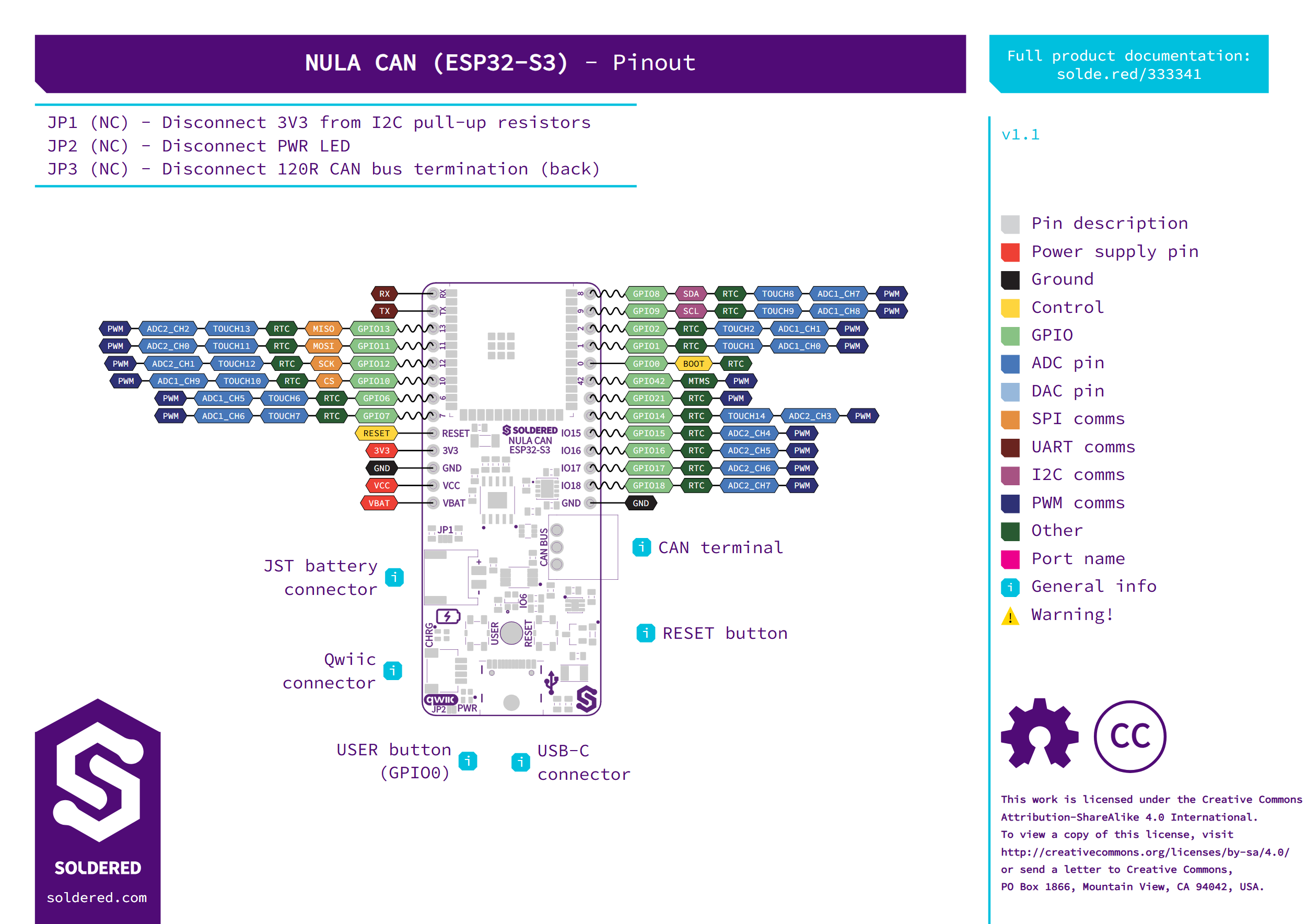
Pin details
| Pin marking | Pin name | Description |
|---|---|---|
RX, TX | GPIO44, GPIO43 | UART0 receive and transmit. The CH340K USB-to-serial chip is wired here, so these carry Serial and the uploads. |
13, 11, 12, 10 | GPIO13, GPIO11, GPIO12, GPIO10 | SPI: MISO, MOSI, SCK and CS. |
8, 9 | GPIO8, GPIO9 | I2C: SDA and SCL, shared with the Qwiic connector, with 10 kΩ pull-ups to 3.3 V (JP1). |
6 | GPIO6 | GPIO, also the data line of the onboard WS2812B RGB LED. |
0 | GPIO0 | GPIO, also the USER button and the boot pin: held low at reset, the ESP32-S3 starts in download mode. |
7, 2, 1, 42, 21, 14 to 18 | GPIO7, GPIO2, GPIO1, GPIO42, GPIO21, GPIO14 to GPIO18 | General-purpose I/O; see the pinout for ADC, touch and PWM functions. |
RESET | EN | Resets the ESP32-S3 when pulled low, the same as the RESET button. |
3V3 | 3.3 V | Output of the 3.3 V regulator. |
VCC | VCC | The board's main supply: USB power, or the battery when USB is unplugged. The CAN transceiver and the regulator run from it, and you can feed 4.5 to 5.5 V in here to power the CAN side. |
VBAT | VBAT | The battery connector's positive line. |
GND | GND | Ground (one on each header). |
CANL, CANH, GND | CAN bus | The three pins of the CAN terminal block, in this order on the board's underside. CAN TX is GPIO5 and CAN RX is GPIO4; neither is on a header. |
Power supply
The board takes power from the USB-C connector or from a single-cell Li-ion battery on the JST connector:
- USB-C comes in through a 500 mA fuse. While USB is connected it powers the board and charges the battery through the TP4056M charger at 400 mA.
- Battery: when USB is unplugged, the board switches over to the battery on its own. The
+and-next to the JST connector show its polarity. - 3.3 V: a TPS7A26 regulator (500 mA) makes 3.3 V for the ESP32-S3 and the
3V3pin. All GPIO use 3.3 V logic. - CAN transceiver: it needs 4.5 to 5.5 V, which it takes from USB or from the
VCCpin. On battery power alone the CAN side switches off on undervoltage, while the ESP32-S3 keeps running.
Dimensions
- Board size: 26 × 63 mm
- Mounting hole: one, 3.2 mm, between the USER and RESET buttons
Jumpers
All three jumpers are closed by default. Cut one to disconnect what it connects.
| Jumper | Default | Function |
|---|---|---|
| JP1 | Closed | Connects the 10 kΩ I2C pull-up resistors on SDA and SCL to 3.3 V. Cut it to disconnect them. |
| JP2 | Closed | Connects the PWR LED. Cut it to disconnect the LED. |
| JP3 (underside) | Closed | Connects the 120 Ω CAN bus termination between CAN_H and CAN_L. Cut it to remove the termination. |