Quick Start
This board drives up to 16 servos or PWM outputs over I2C. Connect it, install the library for your platform, and run the smallest example to see a channel move.
You program the controller connected to this breakout. The breakout itself is not flashed.
- Arduino
- MicroPython
1. Connect the breakout board
Plug a Qwiic cable into either Qwiic connector on the board and the matching connector on your controller. No soldering needed, and the second Qwiic connector is free for chaining another Qwiic board.
| Controller | Soldered PWM & Servo Driver 16-Channel 12-bit PCA9685 breakout |
|---|---|
| Qwiic connector | Either Qwiic connector |
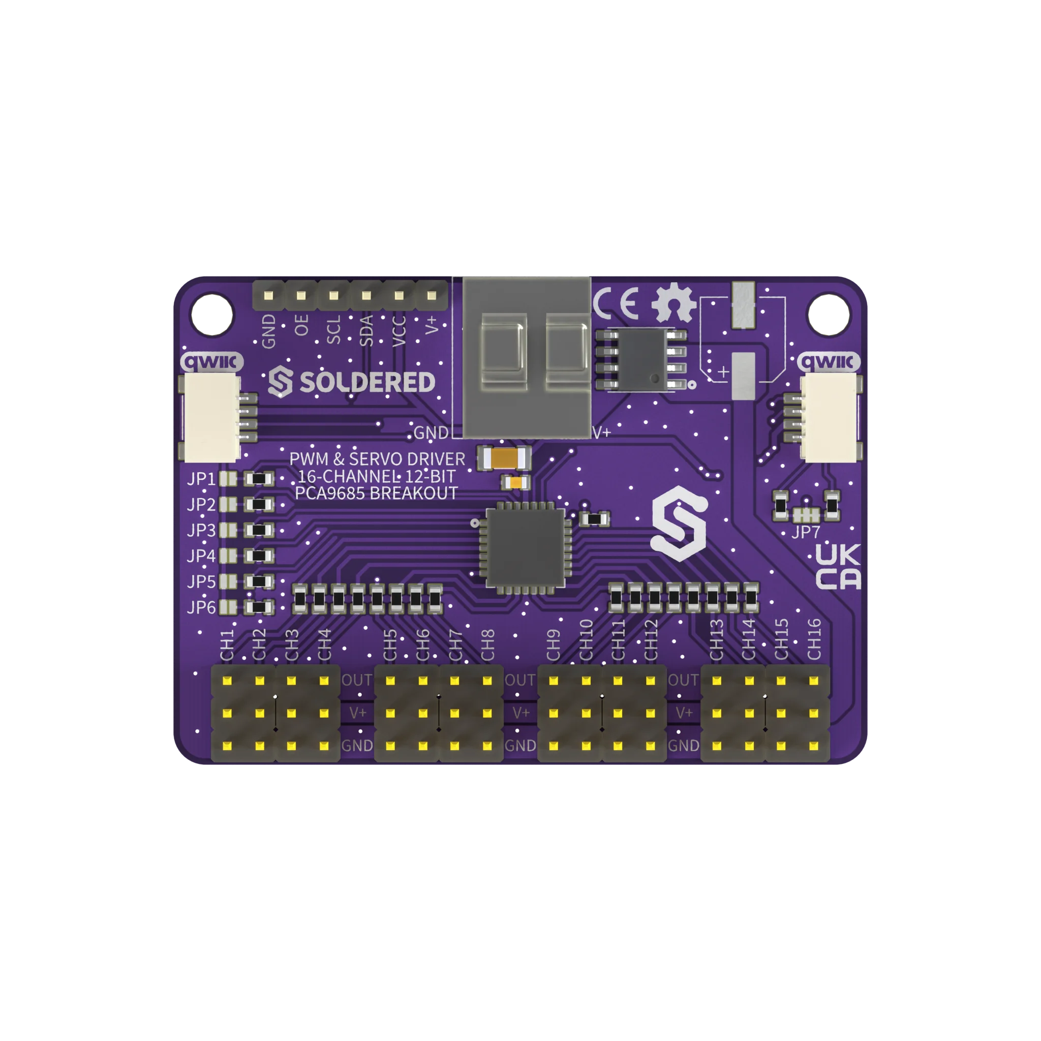
This example only needs the Qwiic connection. The screw terminal (or the header's V+ pad) needs its own supply only once you drive a real servo or PWM load, not for this first test.
2. Install the library
Install Soldered PCA9685 PWM Servo Driver using the Arduino IDE Library Manager, or download it from the source below.
🔗Soldered PCA9685 PWM Servo Driver
Verified Arduino library at commit 1f3aa5a
Tip: downloading from GitHub. On the library's GitHub page, click the green Code button and choose Download ZIP, then add it in Arduino IDE with Sketch → Include Library → Add .ZIP Library....
3. Run the first example
This is Basic_PWM.ino, the library's own example. It ramps the raw PWM duty
cycle on channel 0 from fully off to fully on, over and over.
#include "PCA9685-SOLDERED.h"

PCA9685 pwm;

void setup()
{
    pwm.begin();
    pwm.setPWMFreq(1000); // fast PWM for LEDs/general outputs, not servos
}

void loop()
{
    for (uint16_t duty = 0; duty <= 4095; duty += 32)
    {
        pwm.setPWM(0, 0, duty);
        delay(20);
    }
}
4. Check the result
There is no serial output. Connect an LED (with a suitable resistor) or a scope probe to channel 0's OUT pad, and its brightness or duty cycle ramps up repeatedly, taking a little over 2.5 seconds per ramp.
5. If it does not work
Continue with Troubleshooting and retry this smallest example after each change.
1. Connect the breakout board
Plug a Qwiic cable into either Qwiic connector on the board and the matching connector on your controller. No soldering needed, and the second Qwiic connector is free for chaining another Qwiic board.
| Controller | Soldered PWM & Servo Driver 16-Channel 12-bit PCA9685 breakout |
|---|---|
| Qwiic connector | Either Qwiic connector |
The module auto-detects the I2C pins (SCL 22, SDA 21) on ESP32, ESP8266 and
Soldered Dasduino CONNECTPLUS boards. On any other board, create your own
machine.I2C object and pass it to the constructor.
2. Install the module
Install Soldered PCA9685 MicroPython Library with mpremote, using the
command from the module's own README:
mpremote mip install github:SolderedElectronics/Soldered-PCA9685-MicroPython-Library
On Windows:
python -m mpremote mip install github:SolderedElectronics/Soldered-PCA9685-MicroPython-Library
🔗Soldered PCA9685 MicroPython Library
Verified MicroPython module at commit 611d14a
Tip: downloading from GitHub. Without mpremote, open the module's .py
file on GitHub and click Download raw file, then open it in Thonny and use
File → Save as... → MicroPython device to copy it onto the board.
3. Run the first example
This is pca9685-basicPWM.py, the module's own example. It ramps the raw PWM
duty cycle on channel 0 from fully off to fully on, over and over.
from pca9685 import PCA9685
from utime import sleep_ms

pwm = PCA9685()
pwm.setPWMFreq(1000)  # fast PWM for LEDs/general outputs, not servos

while True:
    for duty in range(0, 4096, 32):
        pwm.setPWM(0, 0, duty)
        sleep_ms(20)
4. Check the result
There is no serial output. Connect an LED (with a suitable resistor) or a scope probe to channel 0's OUT pad, and its brightness or duty cycle ramps up repeatedly, taking a little over 2.5 seconds per ramp.
5. If it does not work
Continue with Troubleshooting and retry this smallest example after each change.