Hardware Details
The HanRun HR913550A does the work. It is an RJ45 socket with the Ethernet isolation transformers built in. This board adds a 13-pin 2.54 mm header with every one of its pins, and two mounting holes. There is no Ethernet chip on the board, and no LED: you connect the header to your own chip.
The KiCad schematic and PCB (unpinned writer-supplied evidence, marked v1.0.) show five parts in total: the socket, the header, two mounting holes and a fiducial marker. There are no resistors, capacitors, ESD parts or jumpers on the board.
Key specifications
| Specification | Value |
|---|---|
| Interface | |
| Interface | None, the Ethernet pairs are on the header |
| Ethernet | 10/100Base-T |
| Qwiic compatible | No |
| Breadboard compatible | Yes |
| Other | |
| Connector | HR913550A RJ45 with integrated magnetics, shielded (HanRun) |
| Isolation | 2250 V DC |
| Header | 13-pin, 2.54 mm pitch, unsoldered |
| Dimensions | 38 × 22 mm |
| Mounting | Two 3.2 mm holes |
| Operating temperature | 0 °C to 85 °C (the socket's rating) |
Pinout
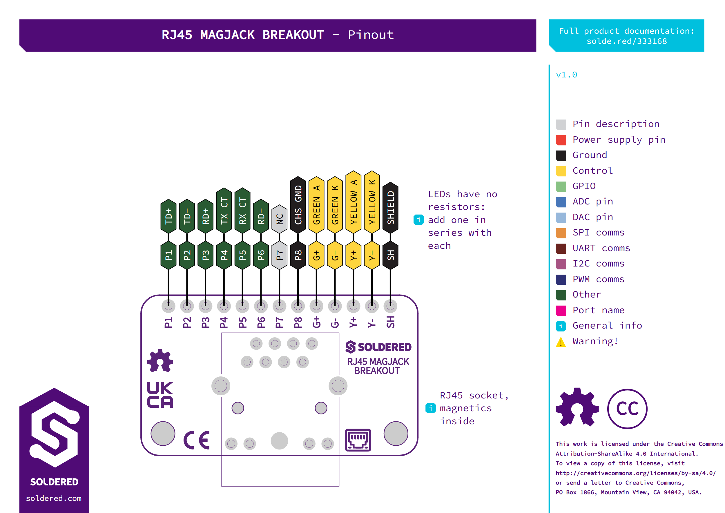
The header is marked P1 to P8, then G+, G-, Y+, Y- and SH.
| Pin marking | Pin name | Description |
|---|---|---|
P1 | TD+ | Transmit pair, positive. Connect it to your Ethernet chip's transmit output. |
P2 | TD- | Transmit pair, negative. |
P3 | RD+ | Receive pair, positive. Connect it to your Ethernet chip's receive input. |
P4 | TX CT | Transmit centre tap, the middle point of the transmit transformer winding. Connect it the way your Ethernet chip's datasheet shows. |
P5 | RX CT | Receive centre tap, the middle point of the receive transformer winding. Connect it the way your Ethernet chip's datasheet shows. |
P6 | RD- | Receive pair, negative. |
P7 | NC | Not connected. |
P8 | CHS GND | Chassis ground. Connect it to the ground of your circuit. Inside the socket it joins the four 75 Ω termination resistors through a 1000 pF, 2 kV capacitor. |
G+ | G_A | Socket pin 9, brought straight to the header. The board has no LED and nothing on it uses this pin. |
G- | G_C | Socket pin 10, brought straight to the header. Not used on the board. |
Y+ | Y_A | Socket pin 12, brought straight to the header. Not used on the board. |
Y- | Y_C | Socket pin 11, brought straight to the header. Not used on the board. |
SH | SHIELD | The socket's metal shield, joined on the board to the socket's shield pads. Connect it to the ground of your circuit. |
Voltage and logic levels
The board has no supply pin and no active parts. The pins carry Ethernet signals, so the voltage levels come from the Ethernet chip you connect.
Connect P8 and SH to the ground of your circuit. The HanRun datasheet says the
same for the chassis ground pin. On the board they are separate: P8 has no
connection to SH or to any other pin.
Dimensions
The board is 38 × 22 mm with rounded corners. The two 3.2 mm mounting holes sit 3 mm in from the two short edges and 3 mm from the long edge on the socket side, 32 mm apart. The socket is centred along the 38 mm side and the 13-pin header is on the other face of the board, along the opposite edge. These positions come from the KiCad PCB (unpinned writer-supplied evidence). The HR913550A itself is 16.04 mm wide, 21.30 mm long and 13.50 mm high, taken from the HanRun datasheet. When you cut a panel opening for the socket, the datasheet suggests 16.54 mm by 14.00 mm.