Hardware Details
Everything the DRV8825 needs is on the board: the driver itself, the sense resistors, the current trimmer and a power indicator. You bring two logic signals, a motor supply and a stepper motor.
Key specifications
| Specification | Value |
|---|---|
| Interface | |
| Interface | Digital GPIO |
| Qwiic | No |
| Microstep resolutions | Full, 1/2, 1/4, 1/8, 1/16, 1/32 |
| Power | |
| Motor supply voltage | 8.2 V to 45 V |
| Logic level | 3V3 or 5V |
| Output current | 1.5 A per phase, 2.2 A per phase with a heatsink |
| Protection | Overcurrent, undervoltage, thermal shutdown |
| Other | |
| Driver IC | DRV8825 |
| Motor type | Bipolar stepper |
| Dimensions | 38 x 22 mm (1.5 x 0.9 inch) |
Pinout
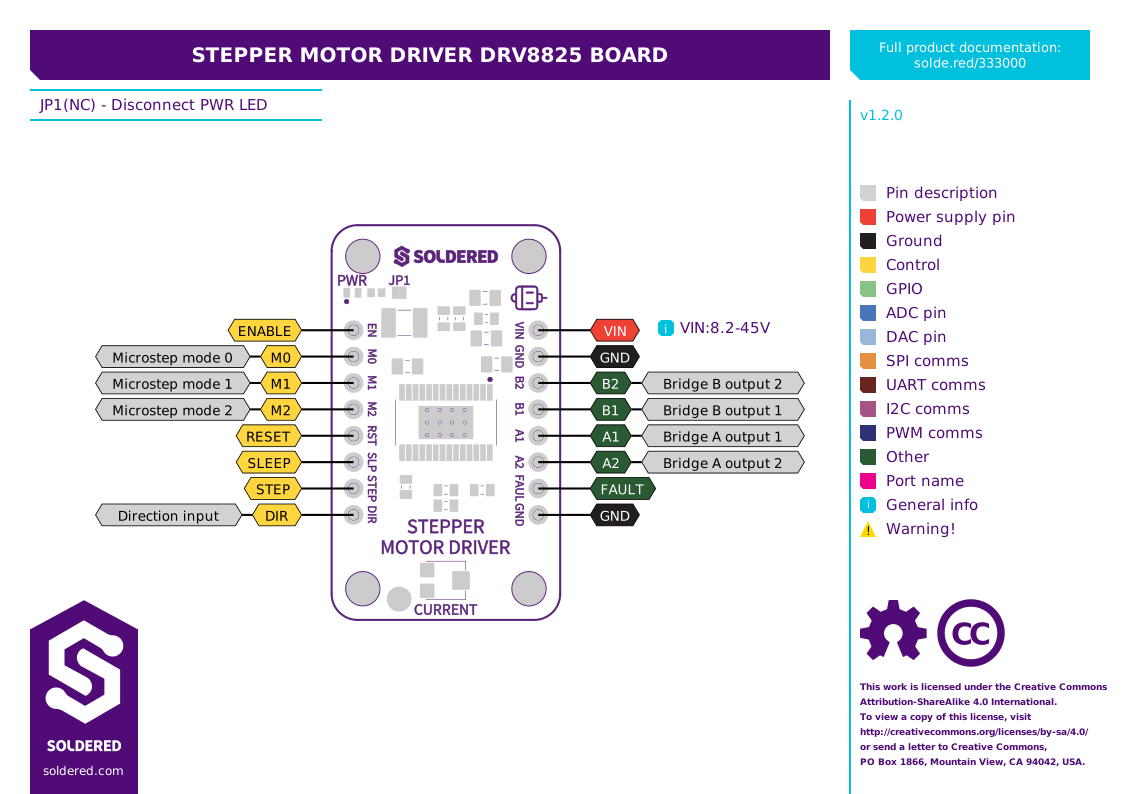
| Pin marking | Pin name | Description |
|---|---|---|
| VIN | Motor supply voltage | 8.2 V to 45 V for the motor. Not the logic supply. Some boards have this pad marked VCC on the back silkscreen; it is the same pad. |
| GND | Motor ground | Ground return for the motor supply. |
| B2 | Bridge B output 2 | Second terminal of one motor coil. |
| B1 | Bridge B output 1 | First terminal of that coil. |
| A1 | Bridge A output 1 | First terminal of the other coil. |
| A2 | Bridge A output 2 | Second terminal of that coil. |
| FAULT | Fault output | Open-drain. Goes low on a fault: overtemperature, overcurrent or undervoltage lockout. |
| GND | Signal ground | Ground reference for the control signals. Connect it to your controller's ground. |
| EN | Enable input | Logic high disables the outputs and the indexer, logic low enables them. Internal pulldown. |
| M0 | Microstep mode 0 | Step mode select, with M1 and M2. Internal pulldown. |
| M1 | Microstep mode 1 | Step mode select, with M0 and M2. Internal pulldown. |
| M2 | Microstep mode 2 | Step mode select, with M0 and M1. Internal pulldown. |
| RST | Reset input | Active low. Initialises the indexer logic and disables the H-bridge outputs. Internal pulldown. |
| SLEEP | Sleep mode input | Logic high enables the driver, logic low enters low-power sleep. Internal pulldown. |
| STEP | Step input | A rising edge moves the indexer one step. Internal pulldown. |
| DIR | Direction input | The level sets the direction of stepping. Internal pulldown. |
Every control input pulls itself low
That matters more than it sounds. RST and SLEEP are the two to watch: both need to be high for the driver to run, and both default low if you leave them unconnected. A board that does nothing at all, with no fault and no heat, is usually one of these two floating.
The rest follow the same rule, and mostly in your favour:
- EN floats low, which is enabled, so you can ignore it entirely if you never need to release the motor.
- M0, M1 and M2 all float low, which is 000, so an unwired board is in full-step mode.
- DIR and STEP float low, so a disconnected controller cannot make the motor move.
Which way the shaft turns for a given DIR level depends on how you wired the coils to A1/A2 and B1/B2. The datasheet says the level selects the direction; it does not say which level is clockwise, because that is not a property of the driver. If the motor runs the wrong way, invert DIR in software or swap the two wires of one coil.
Microstepping
Microstepping splits each full step into smaller increments, which makes the motion smoother and quieter and improves positioning. Set the resolution with M0, M1 and M2:
| M2 | M1 | M0 | Step mode |
|---|---|---|---|
| 0 | 0 | 0 | Full step, 2-phase excitation, at 71% current |
| 0 | 0 | 1 | 1/2 step, 1-2 phase excitation |
| 0 | 1 | 0 | 1/4 step, W1-2 phase excitation |
| 0 | 1 | 1 | 8 microsteps per step |
| 1 | 0 | 0 | 16 microsteps per step |
| 1 | 0 | 1 | 32 microsteps per step |
| 1 | 1 | 0 | 32 microsteps per step |
| 1 | 1 | 1 | 32 microsteps per step |
All three pins pull themselves low, so leaving them unwired gives you full step.
Note the 71% in the first row. In full step the driver runs both phases at 71% of the current you set, not 100%. If a motor feels weaker in full step than in 1/2 step, that is why, and it is by design rather than a fault.
Setting the current limit
Do this before you run a motor for the first time. The trimmer marked CURRENT sets how much current the driver will push through the coils, and it has to stay at or below what your motor is rated for.
The datasheet gives the full-scale chopping current as:
Current limit = Vref / (5 × R_ISENSE)
This board fits 0.2 Ω sense resistors, so 5 × R_ISENSE is exactly 1 and the formula collapses to something easy to remember:
Current limit in amps = Vref in volts
Turn the trimmer while measuring Vref until it reads the current you want. A NEMA17 rated at 350 mA per phase wants 0.35 V. A motor rated at 1.5 A wants 1.5 V.
| Motor rated current | Vref to set |
|---|---|
| 350 mA | 0.35 V |
| 500 mA | 0.50 V |
| 1.0 A | 1.00 V |
| 1.5 A | 1.50 V |
| 2.2 A (needs a heatsink) | 2.20 V |
You can set the limit higher than the motor's nominal rating if the application needs more torque, as long as you stay inside the motor's own specification and the board's 1.5 A limit without a heatsink.
Earlier documentation for this board gave the shortcut Vref = current limit / 2, which is right for a 0.1 Ω design and wrong for this one. Following it sets the limit to half the current you intended, so the motor runs weak and may skip steps under load. Use the figures above.
Voltage and logic levels
| Connection | Supported voltage | Notes |
|---|---|---|
| Motor supply (VIN) | 8.2 V to 45 V | Separate from the controller. Put a capacitor across it at the board. |
| Control inputs | 3V3 or 5V logic | Works directly with both 3.3 V and 5 V controllers. |
Powering a stepper motor from your microcontroller's 5 V rail may appear to work but is not recommended: the current draw causes voltage drops and brownouts.
Below 8.2 V the driver enters undervoltage lockout and pulls FAULT low rather than driving the motor, so the lower bound is a real limit and not a recommendation.
Dimensions
- Dimensions: 38 x 22 mm (1.5 x 0.9 inch)
- Header pin holes: 1.5 mm
- Screw holes: M3 (3.2 mm diameter)
Jumpers
| Jumper | Default | Function |
|---|---|---|
| JP1 | Closed | Connects the PWR indicator LED. Cut it to disconnect the LED and save that current. |